Installation and Operation Guide
2101 Field Wizard
Page
Foreword
Contact Information
Page
2101 Field Wizard
Table of Contents
Section 2 Preparation and Installation
Section 1 Introduction
Appendix B Accessories
Section 5 Maintenance
Appendix A Replacement Parts
Appendix C Material Safety Data Sheets
List of Tables
2101 Field Wizard Table of Contents
2101 Field Wizard Table of Contents
2101 Field Wizard
Section 1 Introduction
1.1 Introduction 1.2 Product Description
Figure 1-1 Field Wizard Keypad and Display
1.3 Identifying Module Components
2101 Field Wizard Section 1 Introduction
2101 Field Wizard Section 1 Introduction
Table 1-1 Field Wizard Components - Side View
Figure 1-2 Field Wizard Components - Side View
Item No
Figure 1-3 Field Wizard Components - Bottom View
Table 1-2 Field Wizard Components - Bottom View
2101 Field Wizard Section 1 Introduction
Item No
Figure 1-4 Model 2101 Field Wizard Connector Pins
Table 1-3 2101 Field Wizard Technical Specifications
Table 1-4 Field Wizard Connector Pins
G FA EB DC
2101 Field Wizard Section 1 Introduction
1.4 Safety Symbols and Hazard Alerts
1.5 Technical Service
2101 Field Wizard
Section 2 Preparation and Installation
2.1 Unpacking Instructions
2.2 Safety 2.3 Connecting To Flowlink
2101 Field Wizard Section 2 Preparation and Installation
Figure 2-2 Connecting the Communication Cable to the Field Wizard
2101 Field Wizard Section 2 Preparation and Installation
Figure 2-1 Connecting the AC Adapter to the Field Wizard
Uncap the communication connector on the right side of the Field Wizard and attach the Communications Cable, as shown in Figure 2-2. Connect the other end of the Communications Cable to a serial COM port on the PC
Figure 2-3 Flowlink Site Info Screen
2.4 Connecting To a Site
2101 Field Wizard Section 2 Preparation and Installation
2101 Field Wizard Section 2 Preparation and Installation
Unlocking
2101 Field Wizard Section 2 Preparation and Installation
Unlocking the latch
Locking the latch
Push
Field Wizard’s Lower Connector - Capped
2100 Series Module’s Upper Connector - Capped
2100 Series Module’s Upper Connector - Uncapped
Field Wizard’s Lower Connector - Uncapped
Field Wizard module - push cap into holder
Field Wizard module - uncap the connector
Field Wizard module - unlock the latch
2101 Field Wizard Section 2 Preparation and Installation
Push down and lock the latch
2100 Series Module - uncap the connector
Align the modules
2101 Field Wizard Section 2 Preparation and Installation
Figure 2-4 Data Retrieval Mode Main Display
2101 Field Wizard Section 2 Preparation and Installation
When the Field Wizard is connected to the site, you will hear a beep and then see the display “PLEASE WAIT...” as the unit queries the site for configuration information. When it has obtained that information, it will format it into a display similar to that in Figure
3.2 Field Wizard Keypad
Section 3 Operation
3.1 Introduction
Windows Help format. You can access the help topics for an
Figure 3-1 Field Wizard Keypad and Display
Numeric Keys Power Key Enter Key
2101 Field Wizard Section 3 Operation
If the display is difficult to read, adjust its contrast by holding down the Plus/Minus +/- key while pressing the Down or Up Arrow key until you obtain the desired lighting level
2101 Field Wizard Section 3 Operation
2101 Field Wizard Section 3 Operation
Figure 3-2 Flowlink Site Info Screen
2101 Field Wizard Section 3 Operation
forward slash
Figure 3-3 Field Wizard Connected to a 2150 Site
3.4 Connecting to a Site
2101 Field Wizard Section 3 Operation
2101 Field Wizard Section 3 Operation
3.6 Data Retrieval Mode
3.5 Site Time Synchronization
Figure 3-4 Synchronize Time Display
FUNCTION
Figure 3-5 Data Retrieval Mode Main Display
2101 Field Wizard Section 3 Operation
Figure 3-6 Retrieve Data Display
3.6.1 Retrieve Data Display When you press F1 RETRIEVE from the Main Display, the window shown in Figure 3-6 will be displayed
2101 Field Wizard Section 3 Operation
Figure 3-7 Data Retrieval Status Display
Figure 3-8 Retrieve # Days Display
To clear the number of days and reset it to zero, press F4 CLEAR
2101 Field Wizard Section 3 Operation
Section 3 Operation
When you press F2 LOG from the Main Display, the window
2101 Field Wizard
3.6.2 Data Retrieval Log
To exit the display and return to the Log Display, press F6 EXIT
2101 Field Wizard Section 3 Operation
Figure 3-10 Data Log Details Display
2101 Field Wizard Section 3 Operation
Figure 3-11 Field Wizard Site Setup Display
Figure 3-12 Field Wizard Backlight Mode Settings
If you press F2 NEXT, you will advance to the next module’s Site
2101 Field Wizard Section 3 Operation
2100 Series Site Setup - If you press F2 NEXT and advance to a 2100 Series module, the Setup display shown in Figure 3-13 will appear
Figure 3-13 Site Setup Display
Figure 3-14 Level Calibration Display
3.6.4 Data Display
Figure 3-15 Sensor Diagnostics Display
2101 Field Wizard Section 3 Operation
Figure 3-16 Data Display
Figure 3-18 Standalone Mode Main Display
3.7 Standalone Mode
When you press F5 INFO from the Main Display, the Site Infor
2101 Field Wizard
Figure 3-20 PC Data Synchronization Mode Display
3.8 PC Data Synchronization Mode
Pressing F5 INFO while in the standalone mode will display the
2101 Field Wizard
2101 Field Wizard Section 3 Operation
4.2 Operation
Section 4 Modbus Protocol
4.1 Introduction
2101 Field Wizard
a polling mechanism to repeatedly send a command until a
By accessing these registers you can obtain the current value of
Level, flow, velocity, and temperature data is stored in metric
2101 Field Wizard
2101 Field Wizard Section 4 Modbus Protocol
4.3 Configurations
Figure 4-1 Configuration Example Direct Connection Shown
4.4 Glossary of Terms
2101 Field Wizard Section 4 Modbus Protocol
4.5 Common Acronyms
2101 Field Wizard Section 4 Modbus Protocol
Register
Table 4-1 Modbus ASCII Address 1 Register Definitions
2101 Field Wizard Section 4 Modbus Protocol
Name
Register Numbers
Table 4-2 Modbus ASCII Address 2-N+1 Register Definitions
2101 Field Wizard Section 4 Modbus Protocol
Name
Register Numbers
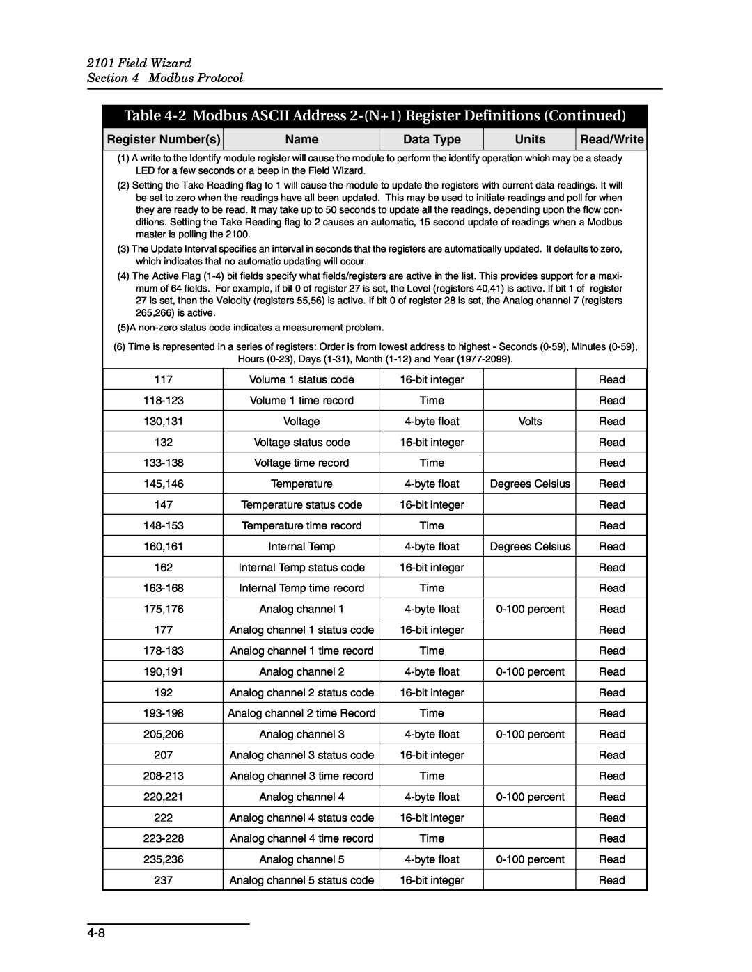
Table 4-2 Modbus ASCII Address 2-N+1 Register Definitions Continued
2101 Field Wizard Section 4 Modbus Protocol
Name
2101 Field Wizard
Table 4-3 Measurement Parameters by Model Number
Table 4-2 Modbus ASCII Address 2-N+1 Register Definitions Continued
Section
2101 Field Wizard Section 4 Modbus Protocol
5.2 Maintenance Kit
Section 5 Maintenance
5.1 Maintenance Overview
5.1.1 Cleaning
5.3.1 Replacing the
5.3 Desiccant
2101 Field Wizard Section 5 Maintenance
Desiccant
Technical Service Dept P.O. Box Lincoln, NE 68501 USA
5.4 Hydrophobic Filter 5.5 How to Obtain Service
2101 Field Wizard Section 5 Maintenance
Phone 800 228-4373 402 FAX 402 E-mail service@isco.com
2101 Field Wizard Section 5 Maintenance
2101 Field Wizard
Appendix A Replacement Parts
A.1 Replacement Parts
Teledyne Isco, Inc
2101 Field Wizard Appendix A Replacement Parts
2101 Field Wizard Appendix A Replacement Parts
2101 Field Wizard Appendix A Replacement Parts
2101 Field Wizard
Appendix B Accessories
B.1 How to Order B.2 General Accessories
Teledyne Isco, Inc
2101 Field Wizard Appendix B Accessories
2101 Field Wizard
Appendix C Material Safety Data Sheets
C.1 Overview
Section 1 - Product and Company Information
MATERIAL SAFETY DATA SHEET
2101 Field Wizard Appendix C Material Safety Data Sheets
Section 2 - Composition / Information on Ingredients
Section 5 - Fire Fighting Measures
2101 Field Wizard Appendix C Material Safety Data Sheets
Section 4 - First Aid Measures
Section 6 - Accidental Release Measures
Section 9 - Physical and Chemical Properties
2101 Field Wizard Appendix C Material Safety Data Sheets
Section 8 - Exposure Controls/Personal Protection
Section 10 - Stability and Reactivity
Section 12 - Ecological Information
2101 Field Wizard Appendix C Material Safety Data Sheets
Section 11 - Toxicological Information
Section 13 - Disposal Information
2101 Field Wizard Appendix C Material Safety Data Sheets
Section 16 - Other Information
LUFXLW�%RDUG
Page
ratio
DECLARATION OF CONFORMITY
fConfo
Standard
Page
DECLARATION OF CONFORMITY
rmity
Conf
Standard
Page
Shipping Address Teledyne Isco, Inc. - Attention Repair Service
Teledyne Isco One Year Limited Factory Service Warranty
Return Authorization
Phone Repair service 800775-2965 lab instruments