5.0 Front Panel
| OPEN | 1 | 2 | 3 |
1 | CLOSE | |||
|
|
|
| |
| OPEN | 4 | 5 | 6 |
2 | CLOSE | |||
|
|
|
| |
| OPEN | 7 | 8 | 9 |
3 | CLOSE | |||
|
|
|
| |
| OPEN | 0 . |
| |
4 | CLOSE PowerPod400 |
| ||
| HASTINGS |
|
| |
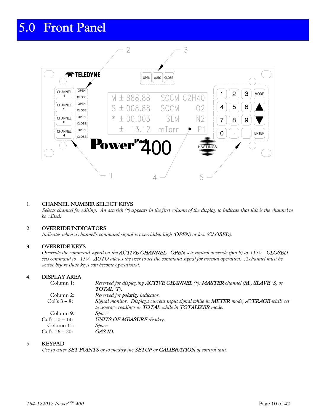
1.CHANNEL NUMBER SELECT KEYS
Selects channel for editing. An asterisk (*) appears in the first column of the display to indicate that this is the channel to be edited.
2.OVERRIDE INDICATORS
Indicates when a channel’s command signal is overridden high (OPEN) or low (CLOSED).
3.OVERRIDE KEYS
Override the command signal on the ACTIVE CHANNEL. OPEN sets control override (pin 8) to +15V. CLOSED sets command to
4.DISPLAY AREA
Column 1: | Reserved for displaying ACTIVE CHANNEL (*), MASTER channel (M), SLAVE (S) or |
| TOTAL (T). |
Column 2: | Reserved for polarity indicator. |
Col’s 3 – 8: | Signal monitor. Displays current input signal while in METER mode, AVERAGE while set |
| to average readings or TOTAL while in TOTALIZER mode. |
Column 9: | Space |
Col’s 10 – 14: | UNITS OF MEASURE display. |
Column 15: | Space |
Col’s 16 – 20: | GAS ID. |
5.KEYPAD
Use to enter SET POINTS or to modify the SETUP or CALIBRATION of control unit.
Page 10 of 42 |