10.6. SETTING LIMIT ALARMS
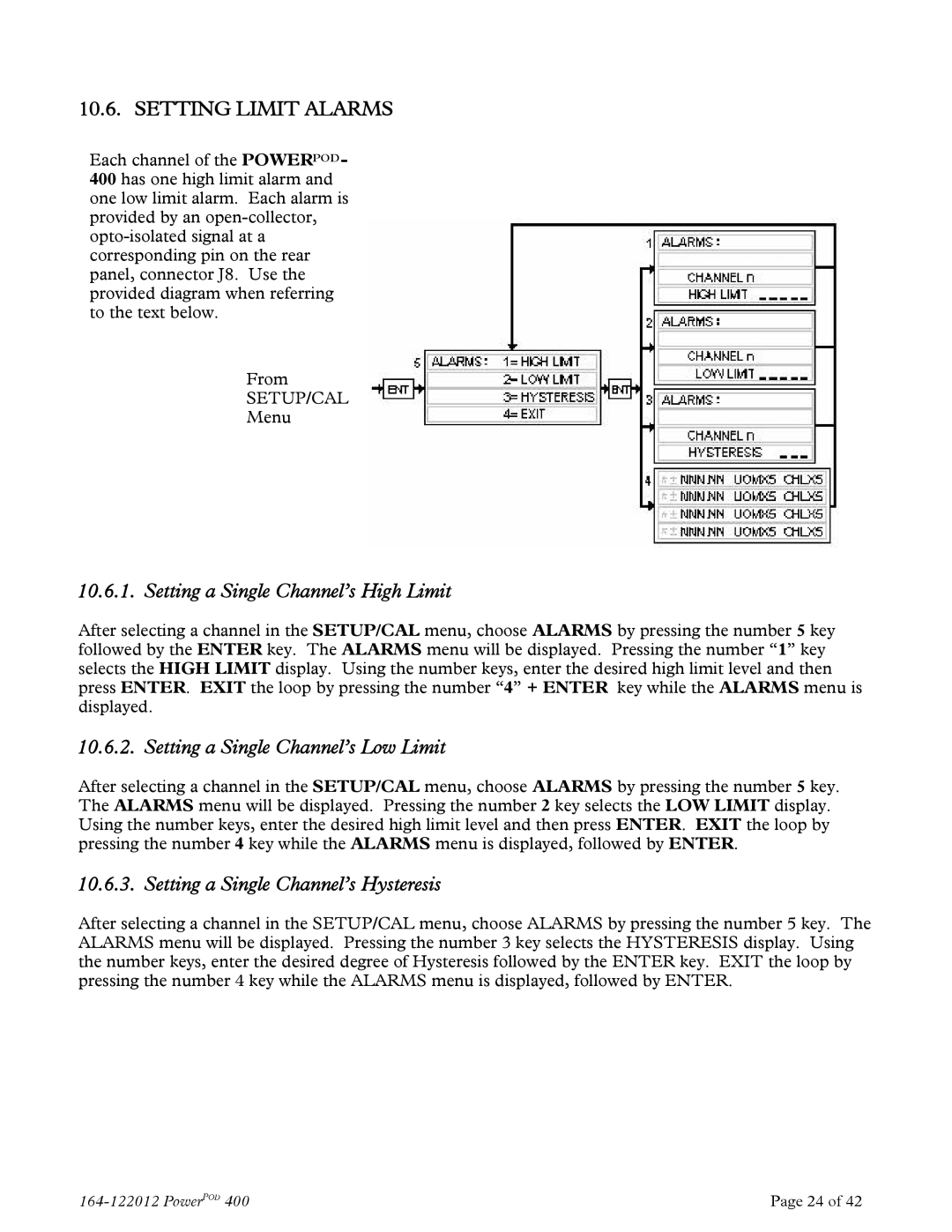
Each channel of the POWERPOD- 400 has one high limit alarm and one low limit alarm. Each alarm is provided by an
From
SETUP/CAL
Menu
10.6.1. Setting a Single Channel’s High Limit
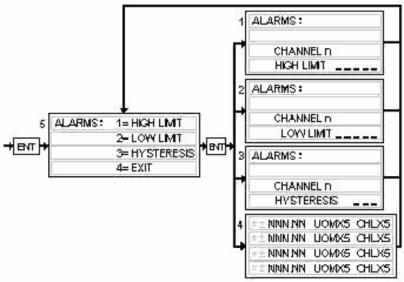
After selecting a channel in the SETUP/CAL menu, choose ALARMS by pressing the number 5 key followed by the ENTER key. The ALARMS menu will be displayed. Pressing the number “1” key selects the HIGH LIMIT display. Using the number keys, enter the desired high limit level and then press ENTER. EXIT the loop by pressing the number “4” + ENTER key while the ALARMS menu is displayed.
10.6.2. Setting a Single Channel’s Low Limit
After selecting a channel in the SETUP/CAL menu, choose ALARMS by pressing the number 5 key. The ALARMS menu will be displayed. Pressing the number 2 key selects the LOW LIMIT display. Using the number keys, enter the desired high limit level and then press ENTER. EXIT the loop by pressing the number 4 key while the ALARMS menu is displayed, followed by ENTER.
10.6.3. Setting a Single Channel’s Hysteresis
After selecting a channel in the SETUP/CAL menu, choose ALARMS by pressing the number 5 key. The ALARMS menu will be displayed. Pressing the number 3 key selects the HYSTERESIS display. Using the number keys, enter the desired degree of Hysteresis followed by the ENTER key. EXIT the loop by pressing the number 4 key while the ALARMS menu is displayed, followed by ENTER.
Page 24 of 42 |