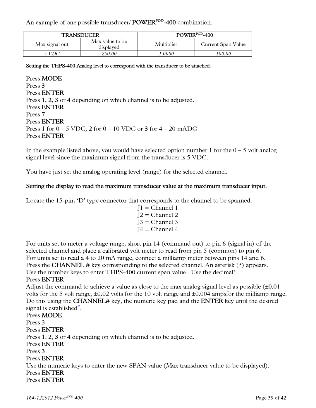
An example of one possible transducer/
| TRANSDUCER |
| |||
Max signal out | Max value to be | Multiplier | Current Span Value | ||
displayed | |||||
|
|
|
| ||
5 VDC |
| 250.00 | 1.0000 | 100.00 | |
Setting the
Press MODE
Press 3
Press ENTER
Press 1, 2, 3 or 4 depending on which channel is to be adjusted.
Press ENTER
Press 7
Press ENTER
Press 1 for 0 – 5 VDC, 2 for 0 – 10 VDC or 3 for 4 – 20 mADC
Press ENTER
In the example listed above, you would have selected option number 1 for the 0 – 5 volt analog signal level since the maximum signal from the transducer is 5 VDC.
You have just set the analog operating level (range) for the selected channel.
Setting the display to read the maximum transducer value at the maximum transducer input.
Locate the
J2 = Channel 2
J3 = Channel 3
J4 = Channel 4
For units set to meter a voltage range, short pin 14 (command out) to pin 6 (signal in) of the selected channel and place a calibrated volt meter to read from pin 5 (common) to pin 6. For units set to read a 4 to 20 mA range, connect a milliamp meter between pins 14 and 6. Press the CHANNEL # key corresponding to the selected channel. An asterisk (*) appears. Use the number keys to enter
Press ENTER
Adjust the command to achieve a value as close to the max analog signal level as possible (±0.01 volts for the 5 volt range, ±0.02 volts for the 10 volt range and ±0.004 ampsfor the milliamp range. Do this using the CHANNEL# key, the numeric key pad and the ENTER key until the desired signal is established#.
Press MODE Press 3 Press ENTER
Press 1, 2, 3 or 4 depending on which channel is to be adjusted. Press ENTER
Press 3
Press ENTER
Use the numeric keys to enter the new SPAN value (Max transducer value to be displayed). Press ENTER
Press ENTER
| Page 39 of 42 |
