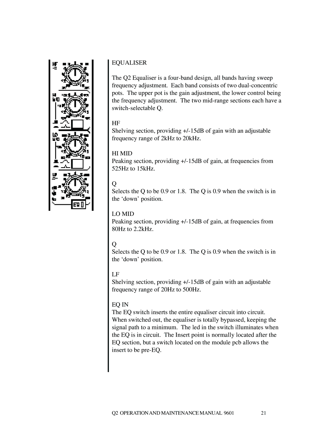
EQUALISER
The Q2 Equaliser is a
HF
Shelving section, providing
HI MID
Peaking section, providing
Q
Selects the Q to be 0.9 or 1.8. The Q is 0.9 when the switch is in the ‘down’ position.
LO MID
Peaking section, providing
Q
Selects the Q to be 0.9 or 1.8. The Q is 0.9 when the switch is in the ‘down’ position.
LF
Shelving section, providing
EQ IN
The EQ switch inserts the entire equaliser circuit into circuit. When switched out, the equaliser is totally bypassed, keeping the signal path to a minimum. The led in the switch illuminates when the EQ is in circuit. The Insert point is normally located after the EQ section, but a switch located on the module pcb allows the insert to be
Q2 OPERATIONAND MAINTENANCE MANUAL 9601 | 21 |