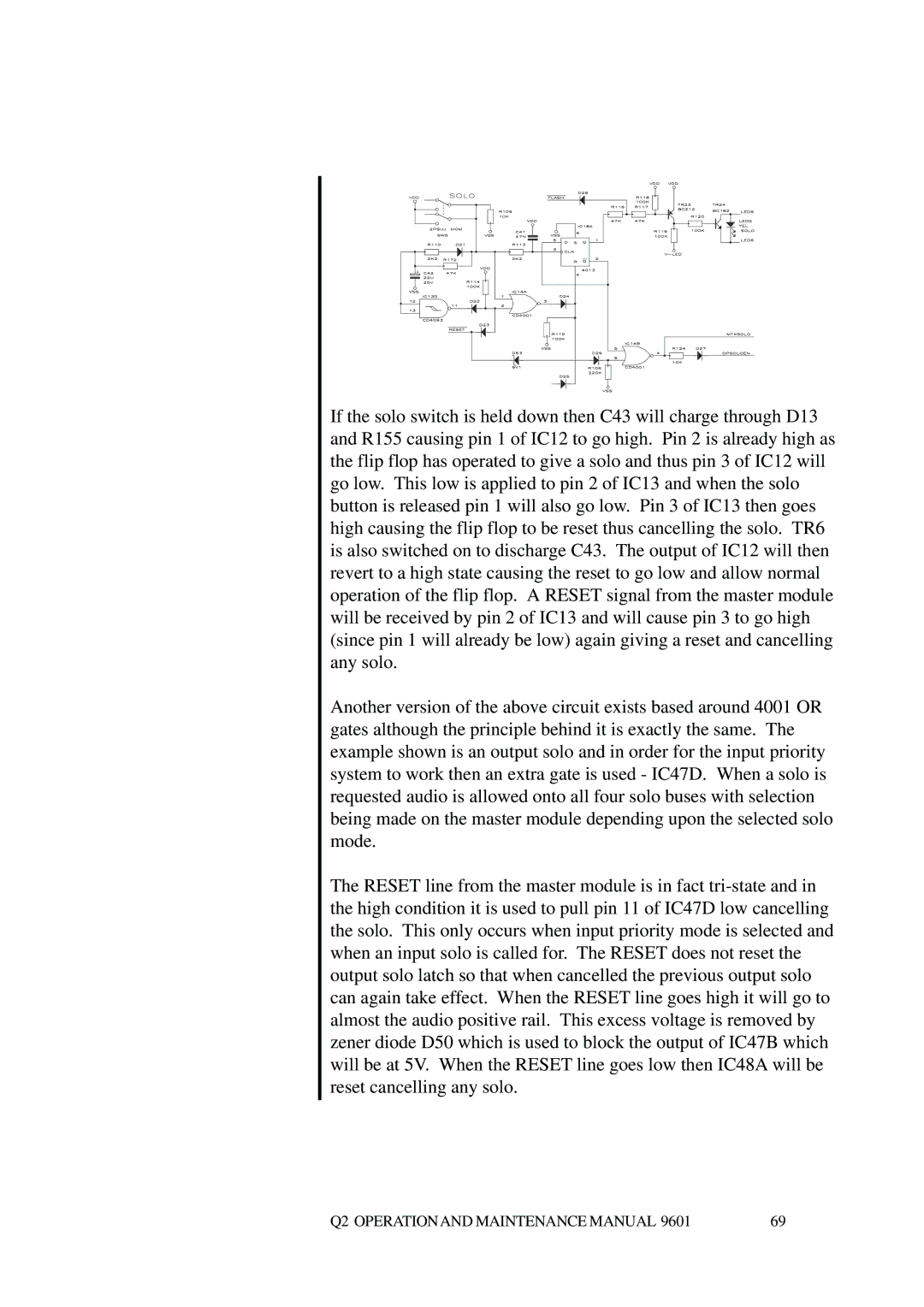
If the solo switch is held down then C43 will charge through D13 and R155 causing pin 1 of IC12 to go high. Pin 2 is already high as the flip flop has operated to give a solo and thus pin 3 of IC12 will go low. This low is applied to pin 2 of IC13 and when the solo button is released pin 1 will also go low. Pin 3 of IC13 then goes high causing the flip flop to be reset thus cancelling the solo. TR6 is also switched on to discharge C43. The output of IC12 will then revert to a high state causing the reset to go low and allow normal operation of the flip flop. A RESET signal from the master module will be received by pin 2 of IC13 and will cause pin 3 to go high (since pin 1 will already be low) again giving a reset and cancelling any solo.
Another version of the above circuit exists based around 4001 OR gates although the principle behind it is exactly the same. The example shown is an output solo and in order for the input priority system to work then an extra gate is used - IC47D. When a solo is requested audio is allowed onto all four solo buses with selection being made on the master module depending upon the selected solo mode.
The RESET line from the master module is in fact
Q2 OPERATIONAND MAINTENANCE MANUAL 9601 | 69 |