Manuals
/
Thermo Products
/
Household Appliance
/
Furnace
Thermo Products
MDA1-75N, MDA1-50N, MHA1-75N, MHA1-100N Appendix E Replacement Parts List MHA1
Models:
MDA1-100N
MDA1-125N
MDA1-75N
MHA1-125N
MHA1-50N
MHA1-100N
MHA1-75N
MDA1-50N
1
53
61
61
Download
61 pages
24.2 Kb
50
51
52
53
54
55
56
57
Install
Parts list
Appendix F Wiring Diagram
To delay fan Set Switch
Maintenance
Diagnostic Features
Checkout Procedure
Adjustment Of Heat Input Rate
Safety
Page 53
Image 53
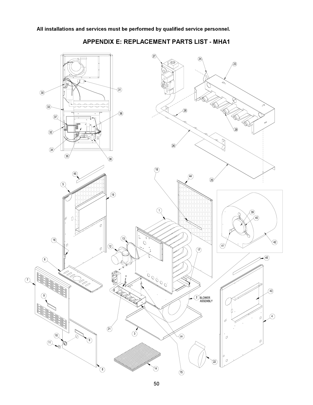
All installations and services must be performed by qualified service personnel.
APPENDIX E: REPLACEMENT PARTS LIST - MHA1
50
Page 52
Page 54
Page 53
Image 53
Page 52
Page 54
Contents
Induced Draft Highboy COUNTERFLOW/HORIZONTAL GAS Furnace
Section Safety II. Installation Guidelines
Page
Shipping Damage
Packaging
Safety
Codes
II. Installation Guidelines
Closet and Alcove Installation
Installation Location
Refer to Figure
Standard Clearances
Non-combustible Material
Plenum Flue or Vent All Models Covered by This Manual
Air for Combustion and Ventilation
MDA1 Horizontal Installation
MDA1 Installed Horizontal
Duct Work and Air Conditioning
Filters/ Filter Installation
Optional Thermo Pride Filter Rack
Use of Non-Thermo Pride Filter Retention Means
Formula
FPM
Venting
Carbon Monoxide Poisoning Hazard
Replacing An Existing Furnace From a Common Vent
Condensing in the Chimney
Page
Page
Vent Connection to Inducer
Inducer Mounting
Automated Literature FAX
Sidewall Venting
Horizontal Size and Length for Sidewall Venting
Horizontal Size and Lengths for Horizontal Vents
General GAS Piping Fire or Explosion Hazard
GAS Piping
Page
Typical Gas Piping
Installation of Natural GAS Piping
Steel Pipe Size for Natural Gas IPS
Installation of Propane GAS Piping
Page
Electrical
Field Wiring and Replacing Wiring
Room Thermostat
Electronic Air Cleaner and Humidifier Connections
Blower and Control Panel
Initial Startup
To delay fan Set Switch
What to do if YOU Smell GAS
To Turn Off Gas To Appliance
Adjustment Of Heat Input Rate
Page
Burner Adjustment
Typical Observation of Main Burner Flames
Setting Supply Air Temperature Rise
Important Remove flue blockage when done
Checkout Procedure
LED will also flash once at power-up
Diagnostic Features
General Inspection
Shut off gas and disconnect power before continuing
House Air Blower
Return Air Filter
Filter Maintenance Procedure
Filter Replacement
VI. Installers Instructions to User
Appendix a Sources for Reference Standards
Sequence of Operations for Heating System
Appendix B Sequence of Operations
Mode of Operation Control System Action
Heating System
Appendix C Troubleshooting Flowcharts
Yes
Is ignitor positioned Correctly?
Does system run until thermostat is satisfied?
Description Part Number QTY
MDA1/MHA1-50S00S4426
Appendix E Replacement Parts List MHA1
Page
Replacement Parts List MDA1
Page
Appendix F Wiring Diagram
Page
MID-EFFICIENCY Highboy GAS Furnace SPECIFICATIONS5
Appendix G MID-EFFICENCY Furnace Specifications
Nominal temp. rise Heating fan speed
Top
Page
Image
Contents