All installations and services must be performed by qualified service personnel.
When venting the MDA1 series through the blower compartment a vent chute (AOPS4941) must be used. Refer to Figure 4. This option requires the removal of the two
The
The
If this venting option is not utilized, the
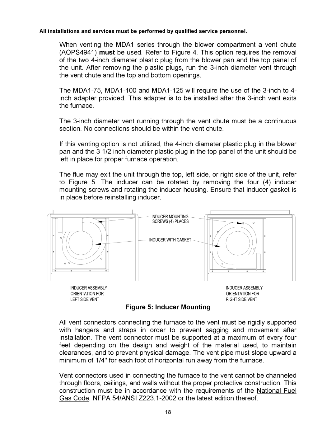
The flue may exit the unit through the top, left side, or right side of the unit, refer to Figure 5. The inducer can be rotated by removing the four (4) inducer mounting screws and rotating the inducer housing. Ensure that inducer gasket is in place before reinstalling inducer.
Figure 5: Inducer Mounting
All vent connectors connecting the furnace to the vent must be rigidly supported with hangers and straps in order to prevent sagging and movement after installation. The vent connector must be supported at a maximum of every four feet depending on the design and weight of the material used, to maintain clearances, and to prevent physical damage. The vent pipe must slope upward a minimum of 1/4" for each foot of horizontal run away from the furnace.
Vent connectors used in connecting the furnace to the vent cannot be channeled through floors, ceilings, and walls without the proper protective construction. This construction must be in accordance with the requirements of the National Fuel Gas Code, NFPA 54/ANSI
18