7. Venting and Combustion Air (cont'd)
7B. Venting and Combustion Air Requirements for Power Vent Drawing Combustion Air from THE INSIDE SPACE and Venting Flue Products to the Outdoors (vent cap is required)
If the environment has a positive pressure and is such that it is not detrimental to combustion air, this system may be installed. To provide combustion air to the heater sufficient air must enter the equipment location to replace that exhausted through the heater vent system. In the past, the infiltration of outside air assumed in heat loss calculations (one air change per hour) was assumed to be sufficient. However, current construction methods using more insulation, vapor barriers, tighter fitting and gasketed doors and windows,
The requirements for combustion and ventilation air depend upon whether the unit is located in a confined or unconfined space. An "unconfined space" is defined as a space whose volume is not less than 50 cubic feet per 1000 BTUH of the installed appliance. Under all conditions, enough air must be provided to ensure there will not be a negative pressure condition within the equip- ment room or space. Follow the specific requirements below for a confined space installation.
Confined Space Installation - Do not install a unit in a con- fined space without providing wall openings leading to and from the space. Provide openings near the floor and ceiling for ventila- tion and air for combustion as shown in Figure 7, depending on the combustion air source as noted in Items 1, 2, and 3 below.
Figure 7 - Confined Space:
A space whose volume is less than 50 cubic feet per 1000 BTUH of the installed appliance input rating
Add total BTUH of all appliances in the confined space and divide by figures below for square inch free area size of each (top and bottom) opening.
1.Air from inside the building
2.Air from outside through duct
3.Air direct from outside
NOTE: For further details on supplying combustion air to a confined space, see the National Fuel Gas Code ANSI Z223.1a (latest edition).
Specific Venting Requirements (read all
before installing)
1) Venter (Flue) Outlet |
| |||
Venter |
|
|
| |
Model Size | 150, 200, 250 | 300, 350, 400 | ||
Outlet | ||||
Outlet Diameter | 5" | 6" | ||
Size: | ||||
|
|
| ||
Venter Outlet Attachment Requirements: | ||||
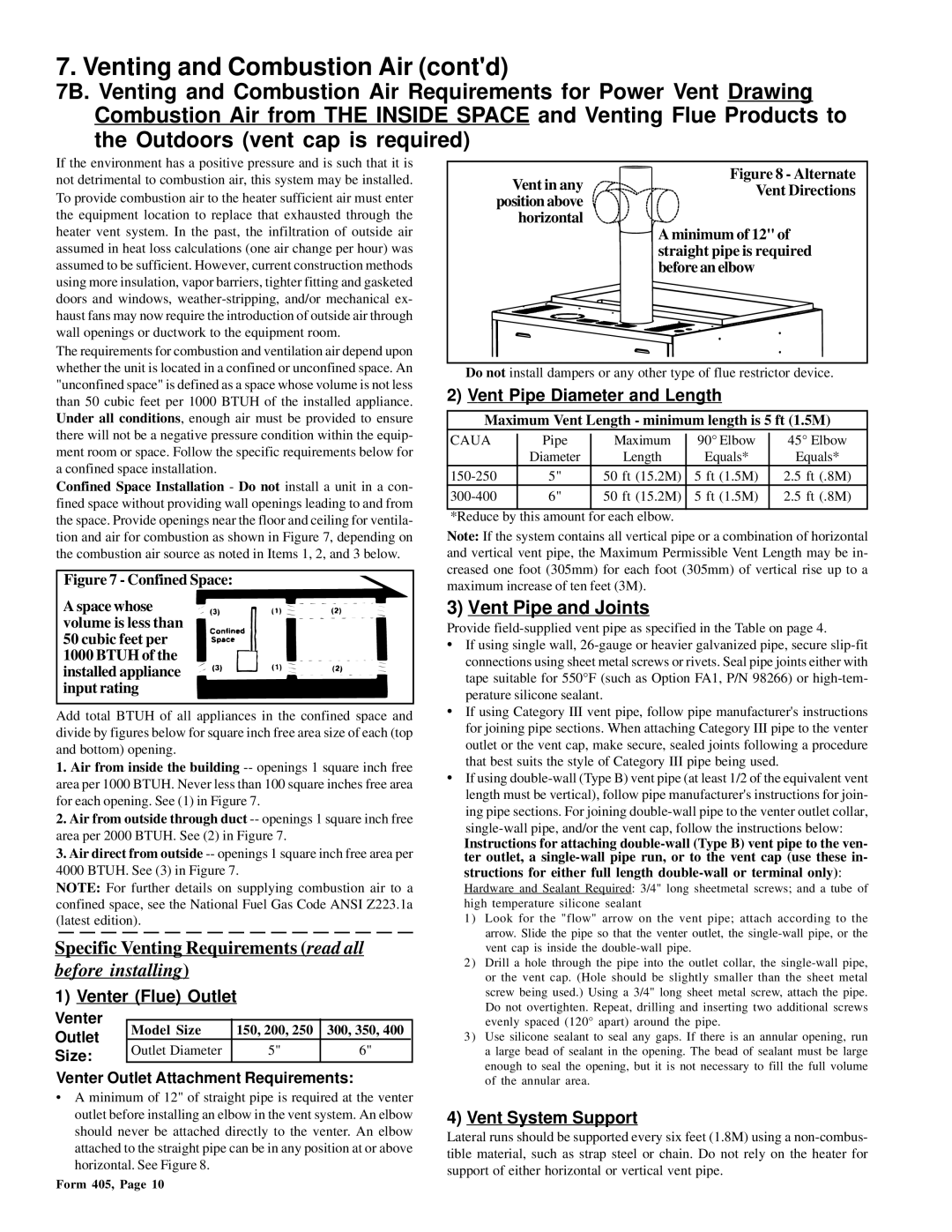
•A minimum of 12" of straight pipe is required at the venter outlet before installing an elbow in the vent system. An elbow should never be attached directly to the venter. An elbow attached to the straight pipe can be in any position at or above horizontal. See Figure 8.
Figure 8 - Alternate
Vent in any | Vent Directions | |
position above | ||
| ||
horizontal |
|
A minimum of 12" of straight pipe is required before an elbow
•Do not install dampers or any other type of flue restrictor device.
2)Vent Pipe Diameter and Length
Maximum Vent Length - minimum length is 5 ft (1.5M)
CAUA | Pipe | Maximum | 90° Elbow | 45° Elbow | ||||
| Diameter |
| Length |
| Equals* | Equals* | ||
5" | 50 | ft (15.2M) | 5 | ft | (1.5M) | 2.5 | ft (.8M) | |
6" | 50 | ft (15.2M) | 5 | ft | (1.5M) | 2.5 | ft (.8M) | |
|
|
|
|
|
|
|
|
|
*Reduce by this amount for each elbow.
Note: If the system contains all vertical pipe or a combination of horizontal and vertical vent pipe, the Maximum Permissible Vent Length may be in- creased one foot (305mm) for each foot (305mm) of vertical rise up to a maximum increase of ten feet (3M).
3)Vent Pipe and Joints
Provide
•If using single wall,
•If using Category III vent pipe, follow pipe manufacturer's instructions for joining pipe sections. When attaching Category III pipe to the venter outlet or the vent cap, make secure, sealed joints following a procedure that best suits the style of Category III pipe being used.
•If using
Instructions for attaching
Hardware and Sealant Required: 3/4" long sheetmetal screws; and a tube of high temperature silicone sealant
1)Look for the "flow" arrow on the vent pipe; attach according to the arrow. Slide the pipe so that the venter outlet, the
2)Drill a hole through the pipe into the outlet collar, the
3)Use silicone sealant to seal any gaps. If there is an annular opening, run a large bead of sealant in the opening. The bead of sealant must be large enough to seal the opening, but it is not necessary to fill the full volume of the annular area.
4)Vent System Support
Lateral runs should be supported every six feet (1.8M) using a
Form 405, Page 10