5)Condensation
Any length of
6)Vent Terminal (Pipe and Vent Cap)
The vent system must be terminated with the type of vent cap approved for use with this heater. The vent cap must be the same size as the vent pipe. Use either a vent cap available from the
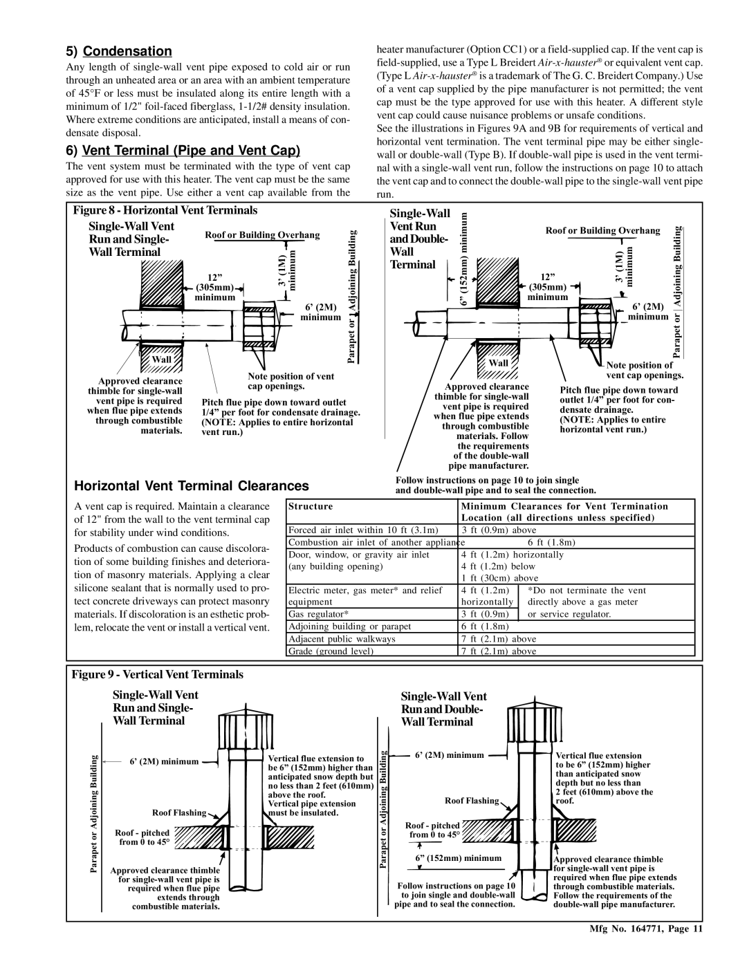
Figure 8 - Horizontal Vent Terminals
heater manufacturer (Option CC1) or a
See the illustrations in Figures 9A and 9B for requirements of vertical and horizontal vent termination. The vent terminal pipe may be either single- wall or
Single-Wall Vent
Run and Single-
Wall Terminal
Wall
Approved clearance thimble for
Roof or Building Overhang | AdjoiningBuilding | ||
12” | 3’(1M) minimum | 6’ (2M) | |
(305mm) |
|
|
|
minimum |
|
|
|
|
| minimum | Parapet or |
|
|
| |
Note position of vent cap openings.
Pitch flue pipe down toward outlet 1/4” per foot for condensate drainage. (NOTE: Applies to entire horizontal vent run.)
Vent Run | Roof or Building Overhang |
| |
and Double- |
| ||
|
|
| |
Wall |
|
|
|
Terminal |
|
|
|
minimum(152mm)6” | 12” | (1M)3’ minimum | AdjoiningBuilding |
(305mm) | |||
minimum | |||
| |||
|
| 6’ (2M) |
|
|
| minimumor | |
Wall |
|
| Parapet |
| Note position of | ||
vent cap openings.
Approved clearance | Pitch flue pipe down toward | |
thimble for | ||
outlet 1/4” per foot for con- | ||
vent pipe is required | ||
densate drainage. | ||
when flue pipe extends | ||
(NOTE: Applies to entire | ||
through combustible | ||
horizontal vent run.) | ||
materials. Follow | ||
| ||
the requirements |
| |
of the |
| |
pipe manufacturer. |
|
Horizontal Vent Terminal Clearances
Follow instructions on page 10 to join single and
A vent cap is required. Maintain a clearance of 12" from the wall to the vent terminal cap for stability under wind conditions.
Products of combustion can cause discolora- tion of some building finishes and deteriora- tion of masonry materials. Applying a clear silicone sealant that is normally used to pro- tect concrete driveways can protect masonry materials. If discoloration is an esthetic prob- lem, relocate the vent or install a vertical vent.
Structure | Minimum Clearances for Vent Termination | ||||
| Location (all directions unless specified) | ||||
Forced air inlet within 10 ft (3.1m) | 3 ft | (0.9m) | above | ||
Combustion air inlet of another appliance |
|
|
|
| 6 ft (1.8m) |
Door, window, or gravity air inlet | 4 | ft | (1.2m) horizontally | ||
(any building opening) | 4 | ft (1.2m) below | |||
| 1 | ft (30cm) above | |||
Electric meter, gas meter* and relief | 4 | ft | (1.2m) | *Do not terminate the vent | |
equipment | horizontally | directly above a gas meter | |||
Gas regulator* | 3 | ft | (0.9m) | or service regulator. | |
Adjoining building or parapet | 6 | ft | (1.8m) |
| |
Adjacent public walkways | 7 | ft (2.1m) | above | ||
Grade (ground level) | 7 | ft (2.1m) | above | ||
Figure 9 - Vertical Vent Terminals
Single-Wall Vent
Run and Single-
Wall Terminal
Building | 6’ (2M) minimum | |
| ||
Adjoining | Roof Flashing | |
| ||
or | Roof - pitched | |
from 0 to 45° | ||
Parapet | ||
Approved clearance thimble | ||
| for | |
| required when flue pipe | |
| extends through | |
| combustible materials. |
Vertical flue extension to be 6” (152mm) higher than anticipated snow depth but no less than 2 feet (610mm) above the roof.
Vertical pipe extension must be insulated.
Parapet or Adjoining Building
Single-Wall Vent
Run and Double-
Wall Terminal
6’ (2M) minimum
Roof Flashing
Roof - pitched from 0 to 45°
6” (152mm) minimum
Follow instructions on page 10 to join single and
Vertical flue extension to be 6” (152mm) higher than anticipated snow depth but no less than
2 feet (610mm) above the roof.
Approved clearance thimble for
Mfg No. 164771, Page 11