8. Duct Connections and Ductwork
Both inlet air ductwork and supply air discharge ductwork are required unless the heater is equipped with an optional inlet base and/or an optional discharge plenum. IMPORTANT NOTE: If a Model ACU cased cooling coil is part of the installation, it must be installed before attaching discharge ductwork. Installation of a filter cabinet is rec- ommended when a cooling coil is installed.
Discharge Duct Connection - The discharge duct connects to the top of the heater or to the outlet of the optional cooling coil cabinet. See Figures 10 and 11. Connect the ductwork plenum to the duct flange as illustrated in Figure 11.
1)The duct connection on the top of the heater has a 90° flange.
2)The duct may either have no flange or a 90° flange.
3)Position ductwork around the outside of the heater flange.
4)If the ductwork has a flange, drill holes vertically through duct flange into the top of the heater and secure with sheetmetal screws. If the ductwork does not have a flange, drill holes hori- zontally through the ductwork and the heater flange; secure with sheetmetal screws.
The cut edges of the metal will be sharp.
If installing an optional filter or filter/mixing cabinet shipped with the heater, attach the cabinet at the "cutout" opening (See Optional Acces- sories, Paragraph 18 or 19). Depending on the cabinet and how it is installed, the inlet opening may be horizontal or vertical.
Attach the ductwork to the heater or to the inlet cabinet.
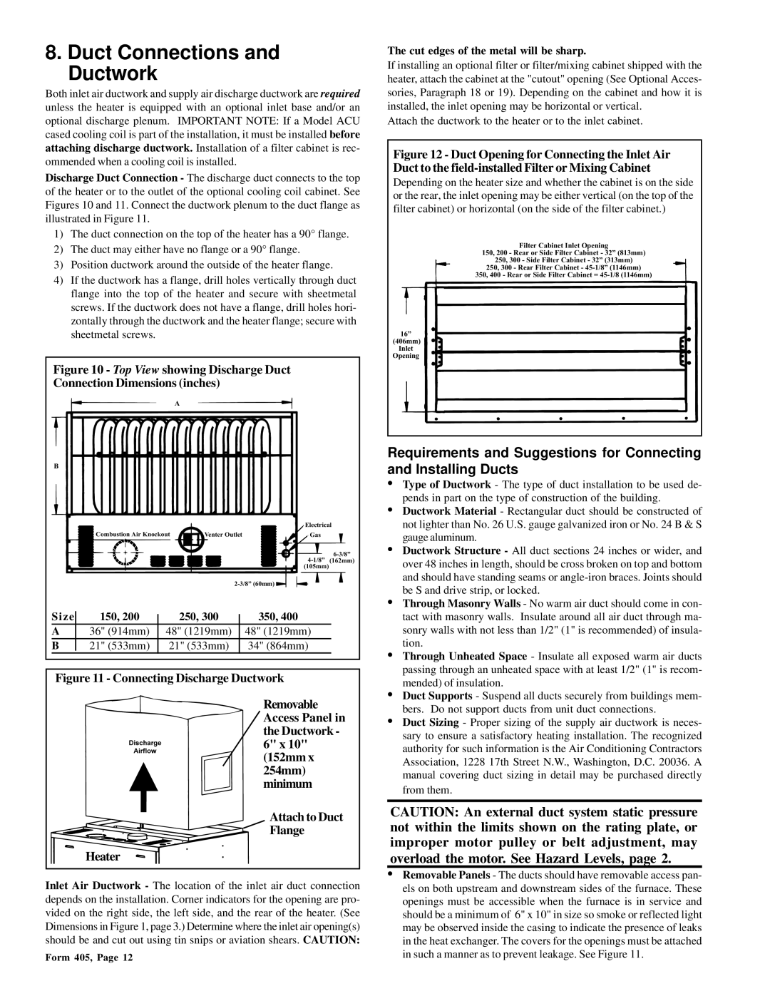
Figure 12 - Duct Opening for Connecting the Inlet Air Duct to the field-installed Filter or Mixing Cabinet
Depending on the heater size and whether the cabinet is on the side or the rear, the inlet opening may be either vertical (on the top of the filter cabinet) or horizontal (on the side of the filter cabinet.)
Filter Cabinet Inlet Opening
150, 200 - Rear or Side Filter Cabinet - 32” (813mm)
250, 300 - Side Filter Cabinet - 32” (313mm)
250, 300 - Rear Filter Cabinet -
350, 400 - Rear or Side Filter Cabinet =
16”
(406mm) Inlet Opening
Figure 10 - Top View showing Discharge Duct Connection Dimensions (inches)
A
B
Combustion Air Knockout | Venter Outlet |
Electrical
Gas
Requirements and Suggestions for Connecting and Installing Ducts
• Type of Ductwork - The type of duct installation to be used de- |
pends in part on the type of construction of the building. |
• Ductwork Material - Rectangular duct should be constructed of |
not lighter than No. 26 U.S. gauge galvanized iron or No. 24 B & S |
gauge aluminum. |
• Ductwork Structure - All duct sections 24 inches or wider, and |
over 48 inches in length, should be cross broken on top and bottom |
and should have standing seams or |
be S and drive strip, or locked. |
• Through Masonry Walls - No warm air duct should come in con- |
Size | 150, 200 |
| 250, 300 |
| 350, 400 |
|
| ||||
A | 36" (914mm) |
| 48" (1219mm) |
| 48" (1219mm) |
B | 21" (533mm) |
| 21" (533mm) |
| 34" (864mm) |
|
|
|
|
|
|
Figure 11 - Connecting Discharge Ductwork
Removable Access Panel in the Ductwork - 6" x 10" (152mm x 254mm) minimum
Attach to Duct
Flange
Heater
Inlet Air Ductwork - The location of the inlet air duct connection depends on the installation. Corner indicators for the opening are pro- vided on the right side, the left side, and the rear of the heater. (See Dimensions in Figure 1, page 3.) Determine where the inlet air opening(s) should be and cut out using tin snips or aviation shears. CAUTION:
Form 405, Page 12
tact with masonry walls. Insulate around all air duct through ma- |
sonry walls with not less than 1/2" (1" is recommended) of insula- |
tion. |
• Through Unheated Space - Insulate all exposed warm air ducts |
passing through an unheated space with at least 1/2" (1" is recom- |
mended) of insulation. |
• Duct Supports - Suspend all ducts securely from buildings mem- |
bers. Do not support ducts from unit duct connections. |
• Duct Sizing - Proper sizing of the supply air ductwork is neces- |
sary to ensure a satisfactory heating installation. The recognized |
authority for such information is the Air Conditioning Contractors |
Association, 1228 17th Street N.W., Washington, D.C. 20036. A |
manual covering duct sizing in detail may be purchased directly |
from them. |
CAUTION: An external duct system static pressure not within the limits shown on the rating plate, or improper motor pulley or belt adjustment, may overload the motor. See Hazard Levels, page 2.
•Removable Panels - The ducts should have removable access pan- els on both upstream and downstream sides of the furnace. These openings must be accessible when the furnace is in service and should be a minimum of 6" x 10" in size so smoke or reflected light may be observed inside the casing to indicate the presence of leaks in the heat exchanger. The covers for the openings must be attached in such a manner as to prevent leakage. See Figure 11.