9. Gas Piping and Pressures
WARNING: This appliance is equipped for a maximum gas supply pressure of 1/2 pound, 8 ounces, or 14 inches water column. Supply pressure higher than 1/2 pound requires installation of an additional
PRESSURE TESTING SUPPLY PIPING
Test Pressures Above 1/2 PSI: Disconnect the heater and manual valve from the gas supply line which is to be tested. Cap or plug the supply line.
Test Pressures Below 1/2 PSI: Before testing, close the manual valve on the heater.
All piping must be in accordance with requirements outlined in the National Fuel Gas Code ANSI Z223.1a (latest edition) or CAN/CGA- B149.1 and B149.2 (See Paragraph 1). Gas supply piping installation should conform with good practice and with local codes.
Unit heaters are orificed for operation with natural gas having a heating value of 1000 (± 50) BTUH per cubic ft or propane gas with a heating value of 2550 BTUH per cubic ft. If the gas at the installation site does not meet these specifications, consult the factory for proper orificing.
Pipe joint compounds (pipe dope) shall be resistant to the action of liquefied petroleum gas or any other chemical constituents of the gas being supplied.
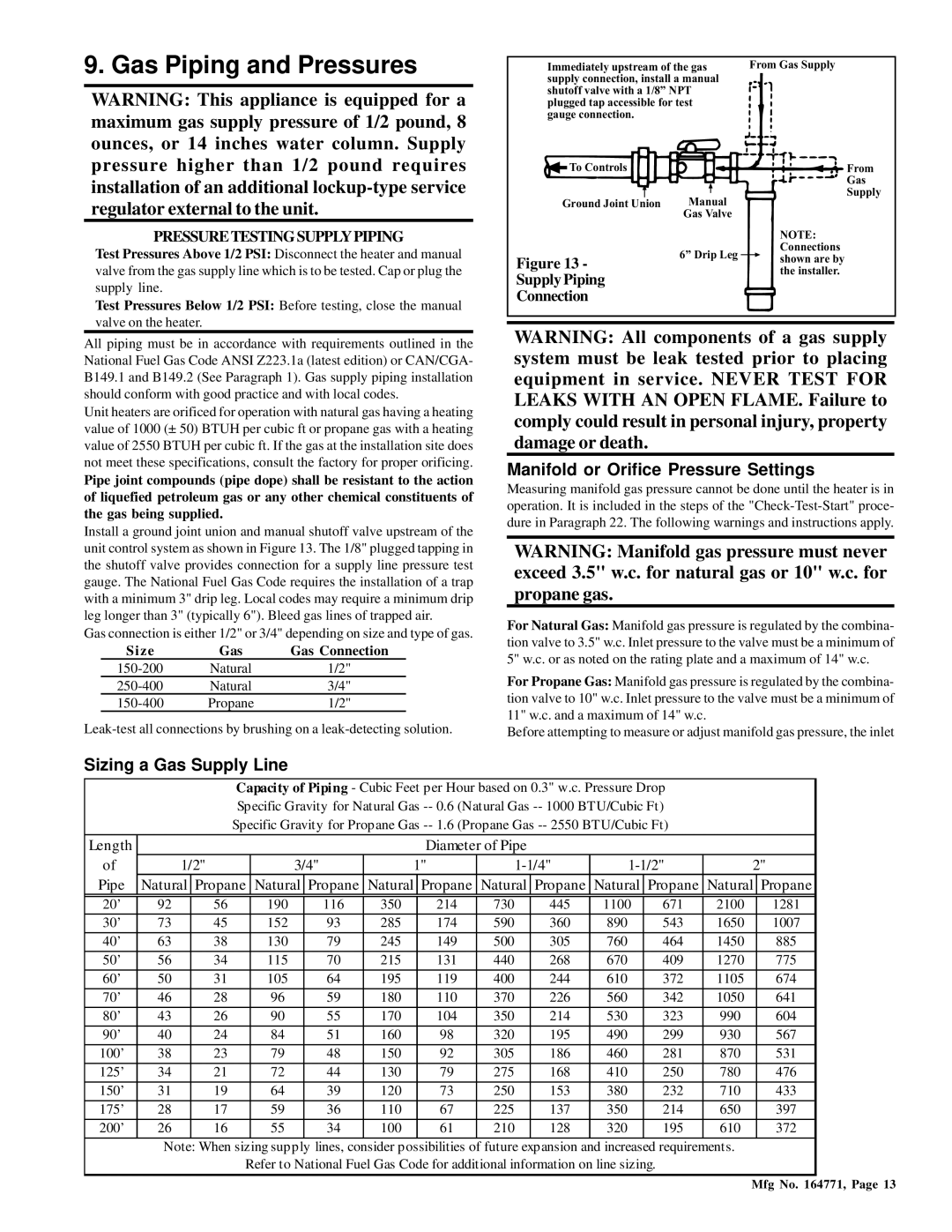
Install a ground joint union and manual shutoff valve upstream of the unit control system as shown in Figure 13. The 1/8" plugged tapping in the shutoff valve provides connection for a supply line pressure test gauge. The National Fuel Gas Code requires the installation of a trap with a minimum 3" drip leg. Local codes may require a minimum drip leg longer than 3" (typically 6"). Bleed gas lines of trapped air.
Gas connection is either 1/2" or 3/4" depending on size and type of gas.
Size | Gas | Gas Connection |
Natural | 1/2" | |
Natural | 3/4" | |
Propane | 1/2" |
Immediately upstream of the gas | From Gas Supply | ||
supply connection, install a manual |
| ||
shutoff valve with a 1/8” NPT |
| ||
plugged tap accessible for test |
| ||
gauge connection. |
|
| |
To Controls |
| From | |
|
| Gas | |
Ground Joint Union | Manual | Supply | |
| |||
| Gas Valve |
| |
|
| NOTE: | |
| 6” Drip Leg | Connections | |
Figure 13 - | shown are by | ||
| |||
Supply Piping |
| the installer. | |
|
| ||
Connection
WARNING: All components of a gas supply system must be leak tested prior to placing equipment in service. NEVER TEST FOR LEAKS WITH AN OPEN FLAME. Failure to comply could result in personal injury, property damage or death.
Manifold or Orifice Pressure Settings
Measuring manifold gas pressure cannot be done until the heater is in operation. It is included in the steps of the
WARNING: Manifold gas pressure must never exceed 3.5" w.c. for natural gas or 10" w.c. for propane gas.
For Natural Gas: Manifold gas pressure is regulated by the combina- tion valve to 3.5" w.c. Inlet pressure to the valve must be a minimum of 5" w.c. or as noted on the rating plate and a maximum of 14" w.c.
For Propane Gas: Manifold gas pressure is regulated by the combina- tion valve to 10" w.c. Inlet pressure to the valve must be a minimum of 11" w.c. and a maximum of 14" w.c.
Before attempting to measure or adjust manifold gas pressure, the inlet
Sizing a Gas Supply Line
Capacity of Piping - Cubic Feet per Hour based on 0.3" w.c. Pressure Drop
Specific Gravity for Natural Gas
Specific Gravity for Propane Gas
Length
of
Pipe
Diameter of Pipe
1/2"3/4"1"1-1/4"1-1/2"2"
Natural ![]() Propane Natural
Propane Natural ![]() Propane Natural
Propane Natural ![]() Propane Natural
Propane Natural ![]() Propane Natural
Propane Natural ![]() Propane Natural
Propane Natural ![]() Propane
Propane
20’ | 92 | 56 |
| 190 | 116 | 350 | 214 | 730 | 445 | 1100 |
| 671 | 2100 | 1281 |
30’ | 73 | 45 |
| 152 | 93 | 285 | 174 | 590 | 360 | 890 |
| 543 | 1650 | 1007 |
|
|
|
|
|
|
|
|
|
|
|
|
|
|
|
40’ | 63 | 38 |
| 130 | 79 | 245 | 149 | 500 | 305 | 760 |
| 464 | 1450 | 885 |
|
|
|
|
|
|
|
|
|
|
|
|
|
|
|
50’ | 56 | 34 |
| 115 | 70 | 215 | 131 | 440 | 268 | 670 |
| 409 | 1270 | 775 |
|
|
|
|
|
|
|
|
|
|
|
|
|
|
|
60’ | 50 | 31 |
| 105 | 64 | 195 | 119 | 400 | 244 | 610 |
| 372 | 1105 | 674 |
|
|
|
|
|
|
|
|
|
|
|
|
|
|
|
70’ | 46 | 28 |
| 96 | 59 | 180 | 110 | 370 | 226 | 560 |
| 342 | 1050 | 641 |
|
|
|
|
|
|
|
|
|
|
|
|
|
|
|
80’ | 43 | 26 |
| 90 | 55 | 170 | 104 | 350 | 214 | 530 |
| 323 | 990 | 604 |
|
|
|
|
|
|
|
|
|
|
|
|
|
|
|
90’ | 40 | 24 |
| 84 | 51 | 160 | 98 | 320 | 195 | 490 |
| 299 | 930 | 567 |
|
|
|
|
|
|
|
|
|
|
|
|
|
|
|
100’ | 38 | 23 |
| 79 | 48 | 150 | 92 | 305 | 186 | 460 |
| 281 | 870 | 531 |
|
|
|
|
|
|
|
|
|
|
|
|
|
|
|
125’ | 34 | 21 |
| 72 | 44 | 130 | 79 | 275 | 168 | 410 |
| 250 | 780 | 476 |
|
|
|
|
|
|
|
|
|
|
|
|
|
|
|
150’ | 31 | 19 |
| 64 | 39 | 120 | 73 | 250 | 153 | 380 |
| 232 | 710 | 433 |
|
|
|
|
|
|
|
|
|
|
|
|
|
|
|
175’ | 28 | 17 |
| 59 | 36 | 110 | 67 | 225 | 137 | 350 |
| 214 | 650 | 397 |
|
|
|
|
|
|
|
|
|
|
|
|
|
|
|
200’ | 26 | 16 |
| 55 | 34 | 100 | 61 | 210 | 128 | 320 |
| 195 | 610 | 372 |
|
|
|
|
|
|
|
|
|
|
|
|
| ||
| Note: When sizing supply lines, consider possibilities of future expansion and increased requirements. |
| ||||||||||||
|
|
| Refer to National Fuel Gas Code for additional information on line sizing. |
|
|
| ||||||||
Mfg No. 164771, Page 13