6. Dimensions
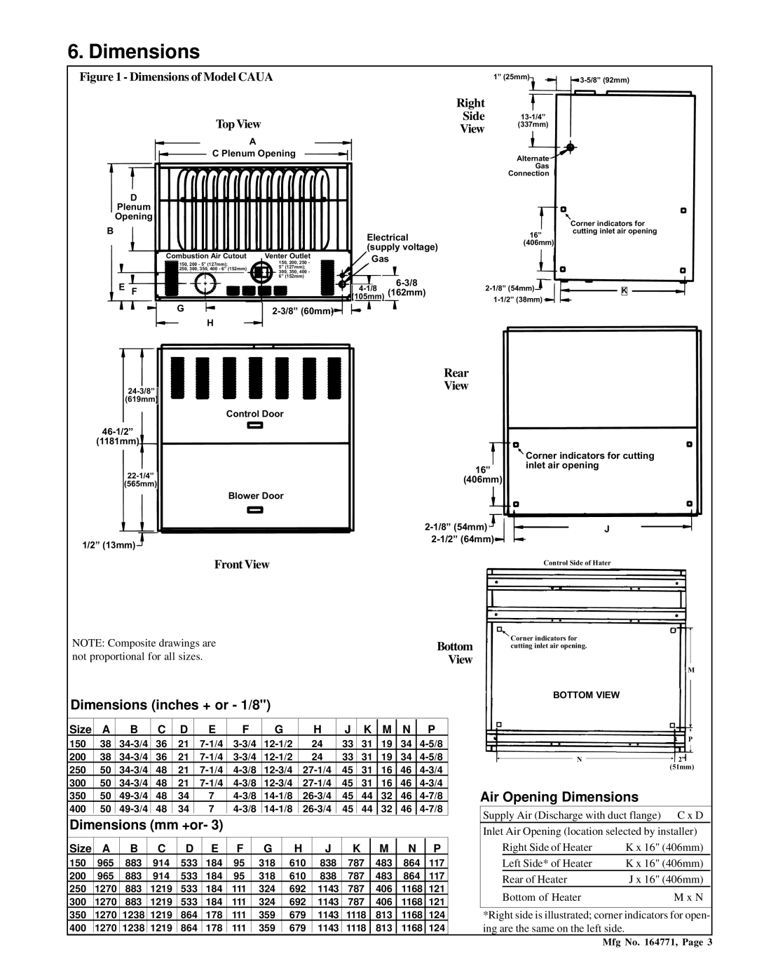
Figure 1 - Dimensions of Model CAUA
Top View
A
C Plenum Opening
D
Plenum
1” (25mm)
Right
Side
View (337mm)
Alternate
Gas
Connection
Opening
B
Combustion Air Cutout | Venter Outlet | |
150, 200 - 5” (127mm); | 150, 200, 250 - | |
250, 300, 350, 400 - 6” (152mm) | 5” (127mm); | |
300, 350, 400 - | ||
| ||
| 6” (152mm) |
E F |
|
G | |
| H |
Electrical (supply voltage)
Gas
(162mm) | |
(105mm) |
|
Corner indicators for
16” cutting inlet air opening (406mm)
K | |
|
(619mm)
Control Door
(1181mm)
(565mm)
Blower Door
1/2” (13mm)![]()
![]()
Rear
View
![]() Corner indicators for cutting
Corner indicators for cutting
16” inlet air opening (406mm)
J | |
|
Front View
Control Side of Hater
NOTE: Composite drawings are | Bottom |
not proportional for all sizes. | View |
Dimensions (inches + or - 1/8")
Size | A | B | C | D | E | F | G | H | J | K | M | N | P |
150 | 38 | 36 | 21 | 24 | 33 | 31 | 19 | 34 | |||||
200 | 38 | 36 | 21 | 24 | 33 | 31 | 19 | 34 | |||||
250 | 50 | 48 | 21 | 45 | 31 | 16 | 46 | ||||||
300 | 50 | 48 | 21 | 45 | 31 | 16 | 46 | ||||||
350 | 50 | 48 | 34 | 7 | 45 | 44 | 32 | 46 | |||||
400 | 50 | 48 | 34 | 7 | 45 | 44 | 32 | 46 | |||||
|
|
|
|
|
|
|
|
|
|
|
|
|
|
Dimensions (mm +or- 3) |
|
|
|
|
|
|
|
| |||||
Size | A | B | C | D | E | F | G | H | J | K | M | N | P |
150 | 965 | 883 | 914 | 533 | 184 | 95 | 318 | 610 | 838 | 787 | 483 | 864 | 117 |
200 | 965 | 883 | 914 | 533 | 184 | 95 | 318 | 610 | 838 | 787 | 483 | 864 | 117 |
250 | 1270 | 883 | 1219 | 533 | 184 | 111 | 324 | 692 | 1143 | 787 | 406 | 1168 | 121 |
300 | 1270 | 883 | 1219 | 533 | 184 | 111 | 324 | 692 | 1143 | 787 | 406 | 1168 | 121 |
350 | 1270 | 1238 | 1219 | 864 | 178 | 111 | 359 | 679 | 1143 | 1118 | 813 | 1168 | 124 |
400 | 1270 | 1238 | 1219 | 864 | 178 | 111 | 359 | 679 | 1143 | 1118 | 813 | 1168 | 124 |
|
|
|
|
|
|
|
|
|
|
|
|
|
|
![]() Corner indicators for cutting inlet air opening.
Corner indicators for cutting inlet air opening.
M
BOTTOM VIEW
| P |
N | 2” |
| (51mm) |
Air Opening Dimensions
Supply Air (Discharge with duct flange) | C x D |
Inlet Air Opening (location selected by installer) | |
Right Side of Heater | K x 16" (406mm) |
Left Side* of Heater | K x 16" (406mm) |
Rear of Heater | J x 16" (406mm) |
Bottom of Heater | M x N |
*Right side is illustrated; corner indicators for open- ing are the same on the left side.
Mfg No. 164771, Page 3