GENERAL (Cont'd)
WARNING: Should overheating occur, or the gas supply fail to shut off, shut off the manual gas valve to the appliance before shutting off the electrical supply.
WARNING: Do not use this appliance if any part has been under water. Immediately call a qualified service technician to inspect the appliance and replace any gas control which has been under water.
CAUTION: Do not locate the heater where it may be exposed to water spray, rain or dripping water.
HAZARD INTENSITY LEVELS
1. DANGER: Failure to comply will result in severe |
personal injury or death and/or property damage. |
2. WARNING: Failure to comply could result in severe |
personal injury or death and/or property damage. |
3. CAUTION: Failure to comply could result in minor |
personal injury and/or property damage. |
1. Installation Codes |
requirements, check with the local gas company or any other local agencies who might have requirements concerning this installation. Before beginning, make preparations for necessary supplies, tools, and manpower.
Shipped-Separate Accessories
•Concentric Adapter and Vent Terminal - If the heater is installed as a
•Filter Cabinet - The return air filter cabinet is shipped separately for field installation over the inlet air opening of the heater. The inlet air opening location is determined by the application. The filter cabinet can attach at the opening on either the rear, the left side, or right side of the unit. Follow the installation instructions included with the cabinet.
•Cased Cooling Coil - Model ACU cooling coils are designed for the Model CAUA heaters. The coil cabinet is shipped separately for installation over the discharge opening of the heater.
•Mixing Cabinet - If outside air is desirable, a mixing cabinet with dampers is available. The mixing cabinet is field attached to the rear of the unit. Check to be sure that the mixing box is the configuration ordered. Follow the installation instructions included with the
•Inlet Base - If an optional inlet base is included, follow the instruc- tions included with the inlet base to select the location. The heater mounts on the inlet base; heater has a bottom inlet air opening.
•Discharge Plenum - The discharge plenum is shipped separately for installation over the discharge opening of the heater. If the dis- charge plenum and a cased cooling coil are part of the installation, the discharge plenum is factory attached to the cooling coil casing.
Also, shipped with the heater are the parts needed to install a conden- sate drain (needed if installing a cooling coil). Other
These units must be installed in accordance with local building codes. In the absence of local codes, in the United States, the unit must be in- stalled in accordance with the National Fuel Gas Code ANSI Z223.1a (latest edition). A Canadian installation must be in accordance with the CAN/CGA B149.1 and B149.2 Installation Code for Gas Burning Ap- pliances and Equipment. These codes are available from CSA Informa- tion Services,
2. Warranty
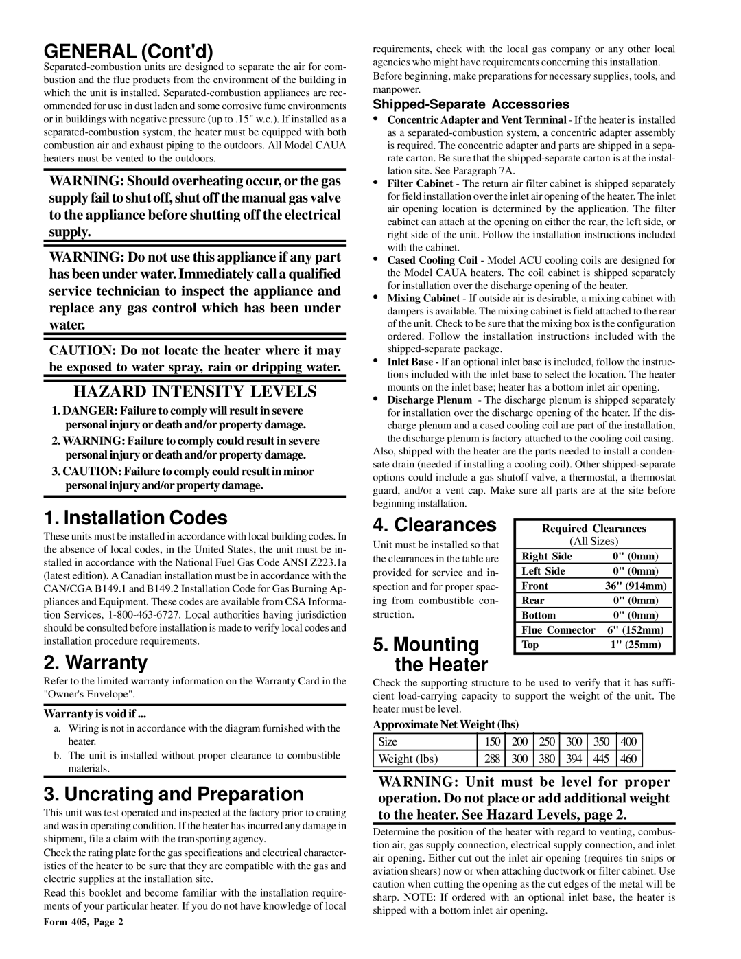
4. Clearances
Unit must be installed so that the clearances in the table are provided for service and in- spection and for proper spac- ing from combustible con- struction.
5.Mounting the Heater
Required Clearances
(All Sizes)
Right Side | 0" (0mm) |
Left Side | 0" (0mm) |
Front | 36" (914mm) |
Rear | 0" (0mm) |
Bottom | 0" (0mm) |
Flue Connector | 6" (152mm) |
Top | 1" (25mm) |
Refer to the limited warranty information on the Warranty Card in the "Owner's Envelope".
Warranty is void if ...
a.Wiring is not in accordance with the diagram furnished with the heater.
b.The unit is installed without proper clearance to combustible materials.
3. Uncrating and Preparation
This unit was test operated and inspected at the factory prior to crating and was in operating condition. If the heater has incurred any damage in shipment, file a claim with the transporting agency.
Check the rating plate for the gas specifications and electrical character- istics of the heater to be sure that they are compatible with the gas and electric supplies at the installation site.
Read this booklet and become familiar with the installation require- ments of your particular heater. If you do not have knowledge of local
Check the supporting structure to be used to verify that it has suffi- cient
Approximate Net Weight (lbs)
Size | 150 | 200 | 250 | 300 | 350 | 400 |
|
|
|
|
|
|
|
|
|
Weight (lbs) | 288 | 300 | 380 | 394 | 445 | 460 |
|
|
|
|
|
|
|
|
|
|
|
|
|
|
|
|
|
WARNING: Unit must be level for proper operation. Do not place or add additional weight to the heater. See Hazard Levels, page 2.
Determine the position of the heater with regard to venting, combus- tion air, gas supply connection, electrical supply connection, and inlet air opening. Either cut out the inlet air opening (requires tin snips or aviation shears) now or when attaching ductwork or filter cabinet. Use caution when cutting the opening as the cut edges of the metal will be sharp. NOTE: If ordered with an optional inlet base, the heater is shipped with a bottom inlet air opening.
Form 405, Page 2