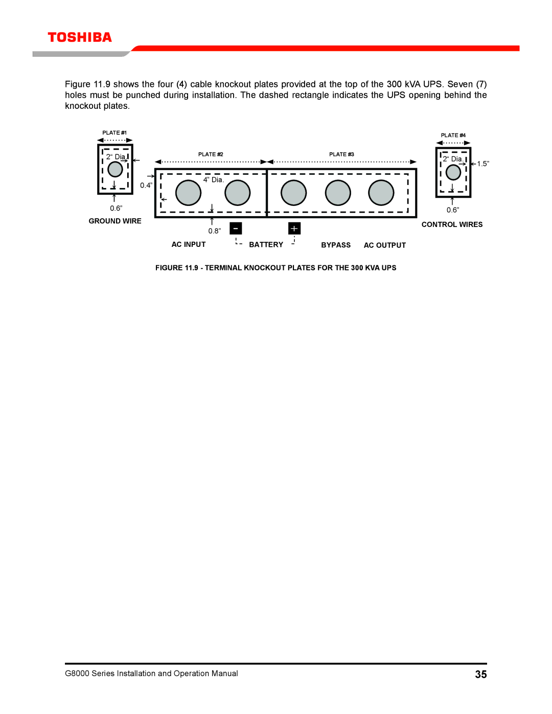
Figure 11.9 shows the four (4) cable knockout plates provided at the top of the 300 kVA UPS. Seven (7) holes must be punched during installation. The dashed rectangle indicates the UPS opening behind the knockout plates.
PLATE #1
Plate #1
2“ Dia.
0.4”
0.6”
GROUND WIRE
PLATE #2 |
| PLATE #3 |
Plate #2 |
| Plate #3 |
4” Dia. |
|
|
0.8” - |
| + |
AC INPUT | BATTERY | BYPASS AC OUTPUT |
PLATE #4
Plate
2“ Dia. | 1.5” |
|
0.6”
CONTROL WIRES
FIGURE 11.9 - TERMINAL KNOCKOUT PLATES FOR THE 300 KVA UPS
G8000 Series Installation and Operation Manual | 35 |