IntegratedHighDefinition LEDTelevisionUser’sGuide
Safety Precautions
Child Safety
Important Safety Instructions
Care
Choosing a location for your LED TV
58 TV
Important notes about your TV
Copyright
Contents
Menu Layout and Navigation
Using the Remote Control
Setting up your TV
Resetting Factory Defaults Setting up your TV
Setting the sleep timer No Signal Power Down Using Hdmi CEC
Adjusting the audio quality DTS TruSurround
Using the input lock feature
MediaShare Videos, Music, and Photos
Wireless LAN and your Health
Using the Hdmi settings feature Hdmi 12, or 3 RGB Range
Color Temperature
Using the TV in a wireless LAN environment...100
Troubleshooting
USB
129
Safety icons
Introduction
Features
1920 x 1080 output resolution
Energy Star qualified
Overview of installation, setup, and use
Read Important notes about your TV on
TV front and side panel controls and connections
TV back panel connections
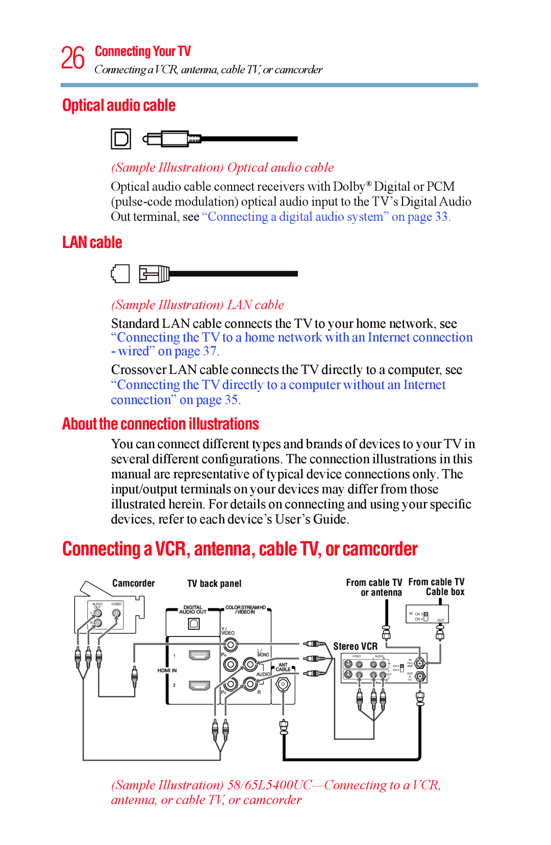
Sample Illustration 58/65L5400UC Back panel connections
Introduction
Sample Illustration Coaxial cable
Overview of cable types
Coaxial F-type cable
Hdmi cable with Hdmi Logo
Standard A/V cables red/white/yellow
Component video cables red/green/blue
Hdmi cables provide the best audio and picture quality
About the connection illustrations
Optical audio cable
LAN cable
Sample Illustration Optical audio cable
To view the antenna or cable signal
From satellite dish
Connecting an Hdmi or DVI device to the Hdmi input
Sample Illustration 58/65L5400UC-HDMIconnections
To view the Hdmi device video
Hdmi CEC connection
Sample Illustration 58/65L5400UC-DVI connections
With the Hdmi Logo
Connecting a digital audio system
Connecting a computer
Connection to the TV’s Hdmi terminal
Connecting to a home network
Edges of the picture may be hidden
Items needed Standard LAN cables Router with a hub
Item Description
Modem DSL or cable Wireless LAN access point
Sample Illustration Removing the remote back cover
Installing batteries
Sample Illustration Installing the batteries
Remote control effective range
Remote control effective range
Learning about the remote control
Sample Illustration Remote control overview
Navigating the menu system on
Learning about the remote control
Display Settings Opens the Display Settings menu
Picture Picture Mode
Reset
Store
Timers Sleep Timer
Setup Hdmi CEC Player
On / Off Parental PIN Setup
Maximum of 12 hours GameTimer
Sample Image Navigating the menu system
System Information
Auto Demo Opens Auto Demo menu
Setting up your TV
Initial Setup
Menu language
Installation setup selection
Sample Image Installation Setup selection
Sample Image Selecting the menu language
Auto Tuning
Storing channels in memory optional
Sample Image Setup menu Installation selection
Sample Image Installation menu Channel selection
Analog channel
Manual Tuning
Setting channel skip
Digital channel
Setting the AV input mode
Setting the time zone
Resetting Factory Defaults
Viewing the system status
Selecting the video input source
Sample Image Input Selection screen
Sample Illustration Hdmi setting pop-up window
Selecting the video input source
Labeling the video input sources
Sample Image Input Labeling screen
Labeling the video input sources
Sample Image Input selection screens
Switching between two channels using Channel Return
Tuning to the next programmed channel
Tuning to a specific channel programmed or unprogrammed
Switching between two channels using SurfLock
Switching between two channels using SurfLock
Selecting the picture size
Sample Illustration Picture size -Full
Full
TheaterWide
Sample Illustration Picture size TheaterWide
Native Mode
Sample Illustration Picture size Native
Sample Illustration Picture size
Normal
Dot by Dot
Sample Illustration Picture size Normal
Sample Image Picture menu Theater Settings selection
Scrolling the TheaterWideTM picture TheaterWide 2 and 3 only
This feature is available when Auto Aspect is set to On
Using the Auto Aspect feature
Using the 43 Stretch
Normal Letter Box TheaterWide Full
Adjusting the picture
Adjusting the picture quality
Sample Image Picture menu Mode selection
Sample Illustration Viewing captions
Using closed captions
Base closed captions
Digital CC settings
Sample Illustration Captions text
Using the Closed caption button
Muting the sound
Adjusting the audio
Using the Digital Audio Selection
Sample Image Levels of mute
Selecting stereo/SAP broadcasts
If the sound is noisy, select Mono to reduce the noise
DTS TruSurround
Adjusting the audio quality
Sound Mode
Stable Sound
Enter a new PIN code
Using the Dolby Digital Dynamic Range Control feature
Selecting the PIN code
Forgotten PIN code
Using the input lock feature
Locking channels
Using the GameTimer
Using the panel lock feature
Sample Illustration Locks menu Panel Lock selection
Using MediaShare with a USB device or a Media Server
MediaShare Videos, Music, and Photos
Non-supported characters will be replaced with a square
Sample Image MediaShare open screen
Auto Start function
To open the MediaShare
Multi View
Sample Image MediaShare setup screen
Viewing photo files
Viewer will open even if there are no photo or music files
Slide show
Picture size functions are disabled
Single view
Playing music files
Sample Image MediaShare music list
Viewing photo files and playing music files at the same time
Playing video files
MediaShare Videos,ToMusic,set the repeatand Phmotosde
To unregister your device
DivX
To register your TV to a DivX account
Setting the sleep timer
To playback DivX HD content
Default setting for this feature is On
No Signal Power Down
Using Hdmi CEC
Available remote control key functions
Hdmi CEC Player Control menu functions
Hdmi CEC input source selection
Volume and Mute controls of Audio Receiver
Setup Menu Accesses the setup menu of a selected device
CEC Player Control menu disappears
Setting up Hdmi CEC
Other Hdmi CEC functions
Hdmi Information Display
Using the Hdmi settings feature
Hdmi 12, or 3 RGB Range
Limited
Displaying TV status information
Sample Illustration Info banner
Understanding the last mode memory feature
Using the TV’s Advanced Features
Base Color Adjustment
Cool Blueish Medium Neutral Warm Reddish
Color Temperature
Static Gamma
Dynamic Contrast
Cinema Mode
DynaLightTM
DNR Dynamic Noise Reduction
This feature may not work properly depending on the content
Noise Reduction
Edge Enhancer
Using your home network
When using a Wireless network connection
Setting up the Network
Wireless Setup
Easy Setup using PBC Push button configuration
Easy Setup using PIN Personal Identification Number
Assisted Setup
Manual Setup
This item is grayed out when Encryption is set to None
Wireless Information
Other items are grayed out when Auto Setup is set to On
Advanced Network Setup IP Address Setup
When manually setting the IP Address, set Auto Setup to Off
DNS Setup
IP address field numbers must be between 0
DNS address field numbers must be between 0
MAC Address
Network Connection Test
Shift
Sample Illustration Software keyboard
Text entry field
Return
Enter text using the software keyboard
An Internet connection is required
If the network is not available, a warning message appears
Using the TV Application Services features
Watching movies with Netflix
YouTubeTM
Troubleshooting
General troubleshooting
Picture problems
Onscreen Demo Pop-up
Sound problems
Noisy picture
Remote control problems
Channel tuning problems
Network problems
Closed caption problems
Hdmi problems
No Hdmi CEC operation
No network connection
Media server name is not displayed
Wireless network problems
MediaShare problems
If the problem persists after trying the solutions
Specifications
Power source
Speaker type
Digital audio output
Wireless connection
Dimensions with stand
Ethernet
Operating conditions
Supplied accessories
Weight mass
800 x 60.317 Hz 37.879 kHz 40.000 MHz
Hdmi signal formats
640 x 59.940 Hz 31.469 kHz 25.175MHz
1024 x 60.004 Hz 48.363 kHz 65.000 MHz
DNR Color Temperature
Using closed captions 66
Cinema Mode Noise Reduction
Choosing a location for your
About the connection illustrations
Exhibit C Index 135 Features 18, 20 Full
Features Overview of installation, setup, and use
Standard A/V cables red/white/ yellow
Using 75 picture Adjusting quality 67 picture size
If the problem persists after trying the solutions
Using the Hdmi settings feature Hdmi 1or 2 RGB Range
Navigating the menu system
Using Media Player with a USB device
Selecting the PIN code 73 Specifications
Sound problems
Installing batteries
Base Color Adjustment
Labeling