Notes to Users
Step 4: Network Planning Information
Table
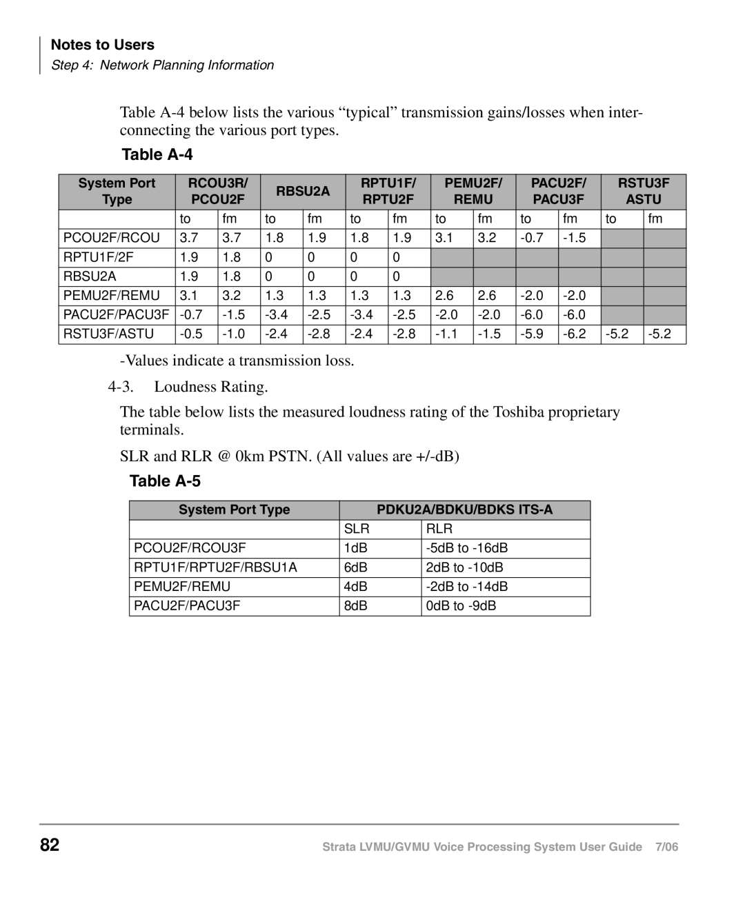
Table A-4
System Port | RCOU3R/ | RBSU2A | RPTU1F/ | PEMU2F/ | PACU2F/ | RSTU3F | |||||||
Type | PCOU2F | RPTU2F | REMU | PACU3F | ASTU | ||||||||
|
| ||||||||||||
| to | fm | to | fm | to | fm | to | fm | to | fm | to | fm | |
PCOU2F/RCOU | 3.7 | 3.7 | 1.8 | 1.9 | 1.8 | 1.9 | 3.1 | 3.2 |
|
| |||
RPTU1F/2F | 1.9 | 1.8 | 0 | 0 | 0 | 0 |
|
|
|
|
|
| |
RBSU2A | 1.9 | 1.8 | 0 | 0 | 0 | 0 |
|
|
|
|
|
| |
PEMU2F/REMU | 3.1 | 3.2 | 1.3 | 1.3 | 1.3 | 1.3 | 2.6 | 2.6 |
|
| |||
PACU2F/PACU3F |
|
| |||||||||||
RSTU3F/ASTU | |||||||||||||
The table below lists the measured loudness rating of the Toshiba proprietary terminals.
SLR and RLR @ 0km PSTN. (All values are
Table A-5
System Port Type |
| PDKU2A/BDKU/BDKS | |
| SLR |
| RLR |
PCOU2F/RCOU3F | 1dB |
| |
RPTU1F/RPTU2F/RBSU1A | 6dB |
| 2dB to |
PEMU2F/REMU | 4dB |
| |
PACU2F/PACU3F | 8dB |
| 0dB to |
82 | Strata LVMU/GVMU Voice Processing System User Guide 7/06 |