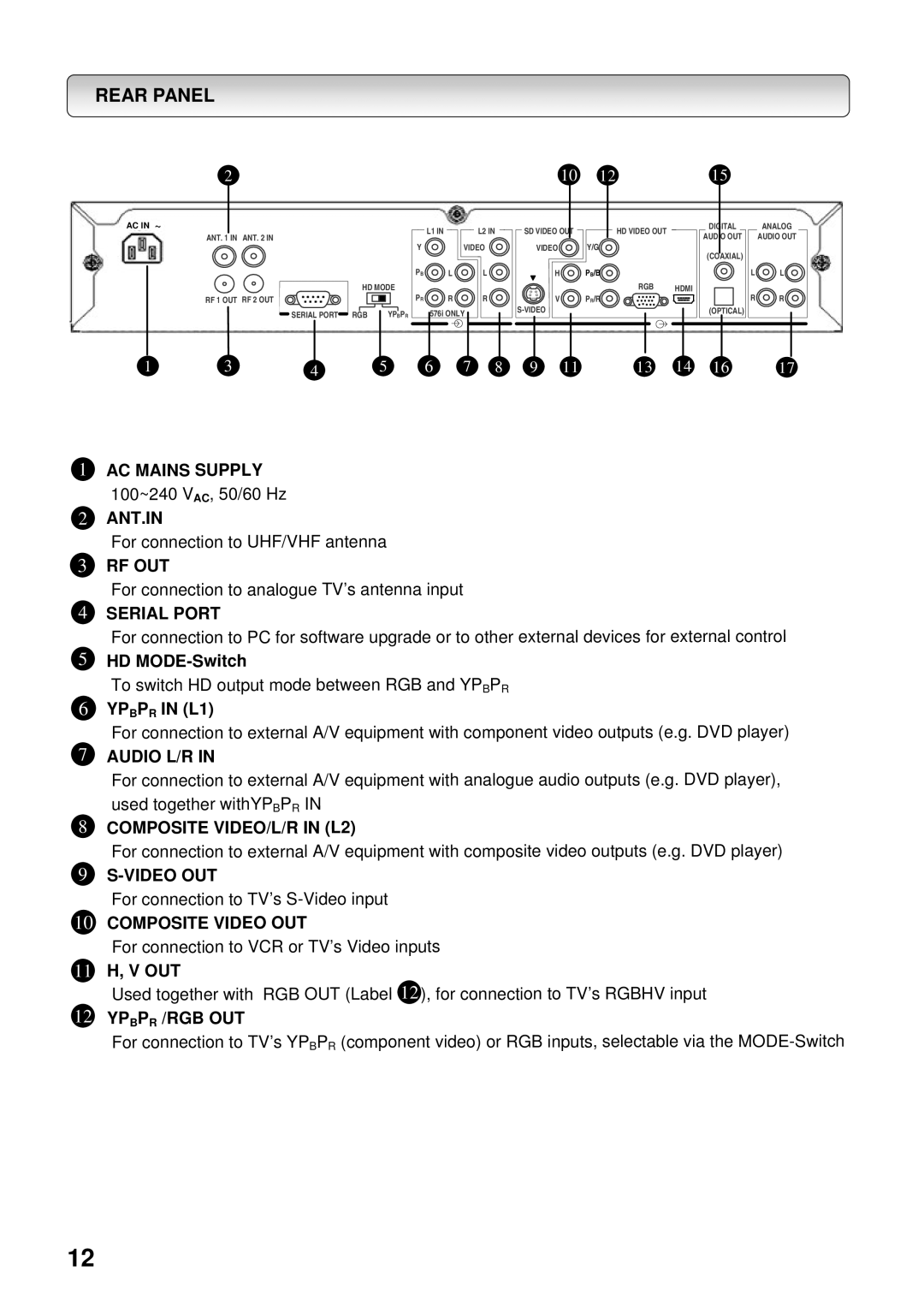
REAR PANEL
2 |
|
AC IN ~ |
|
ANT. 1 IN | ANT. 2 IN |
L1 IN | L2 IN |
Y | VIDEO |
1012
SD VIDEO OUT | HD VIDEO OUT |
VIDEO | Y/G |
15
| DIGITAL |
|
|
| ANALOG |
AUDIO OUT |
|
| AUDIO OUT | ||
HD MODE | |
RF 1 OUT RF 2 OUT |
|
SERIAL PORT RGB | YPBPR |
PB | L | L |
PR | R | R |
| 576i ONLY |
|
H | PB/B |
|
| RGB | HDMI |
V | PR/R |
|
|
|
(COAXIAL)
(OPTICAL)
L![]() L
L![]()
R![]() R
R![]()
1 | 3 | 4 | 5 | 6 | 7 | 8 | 9 | 11 | 13 | 14 | 16 | 17 |
1
2
3
4
5
6
7
8
9
10
11
12
AC MAINS SUPPLY |
|
|
|
|
|
| |||
100~240 V , 50/60 Hz |
|
|
|
|
|
| |||
|
|
| AC |
|
|
|
|
|
|
ANT.IN |
|
|
|
|
|
| |||
For connection to UHF/VHF antenna |
|
| |||||||
RF OUT |
|
|
|
|
|
| |||
For connection to analogue TV’s antenna input |
|
| |||||||
SERIAL PORT |
|
|
|
|
|
| |||
For connection to PC for software upgrade or to other external devices for external control | |||||||||
HD |
|
|
|
|
|
| |||
To switch HD output mode between RGB and YP | P | R | |||||||
|
|
|
|
|
|
| B |
| |
YP | P |
| IN (L1) |
|
|
|
|
|
|
B | R |
|
|
|
|
|
|
| |
For connection to external A/V equipment with component video outputs (e.g. DVD player) | |||||||||
AUDIO L/R IN |
|
|
|
|
|
| |||
For connection to external A/V equipment with analogue audio outputs (e.g. DVD player), | |||||||||
used together withYP P | R | IN |
|
|
|
| |||
|
|
| B |
|
|
|
|
| |
COMPOSITE VIDEO/L/R IN (L2) |
|
| |||||||
For connection to external A/V equipment with composite video outputs (e.g. DVD player) | |||||||||
|
|
|
|
|
| ||||
For connection to TV’s |
|
| |||||||
COMPOSITE VIDEO OUT |
|
|
|
| |||||
For connection to VCR or TV’s Video inputs |
|
| |||||||
H, V OUT |
|
|
|
|
|
| |||
Used together with RGB OUT (Label 12 ), for connection to TV’s RGBHV input | |||||||||
YP | P | R | /RGB OUT |
|
|
|
|
|
|
B |
|
|
|
|
|
|
| ||
For connection to TV’s YP P | R | (component video) or RGB inputs, selectable via the | |||||||
|
|
|
|
| B |
|
|
| |
12
