1-4. Connections to TV – Video Connection
In the accessory box, you will find two sets of cables: One is the component video cable (with red, green and blue connectors) and the other is the Audio/Video cable (with yellow, white and red connectors).
For better video quality, it is recommended that you use the HDMI cable, the Mini
HD MODE Switch selection is essential for several outputs. Refer to the HD MODE Switch table on page 71 for making the correct switch selection according to your output connection.
You have 6 choices for connecting the video output from the recorder to your TV. Use only one of the following connections (with (a), (b) or (c) being the best choice):
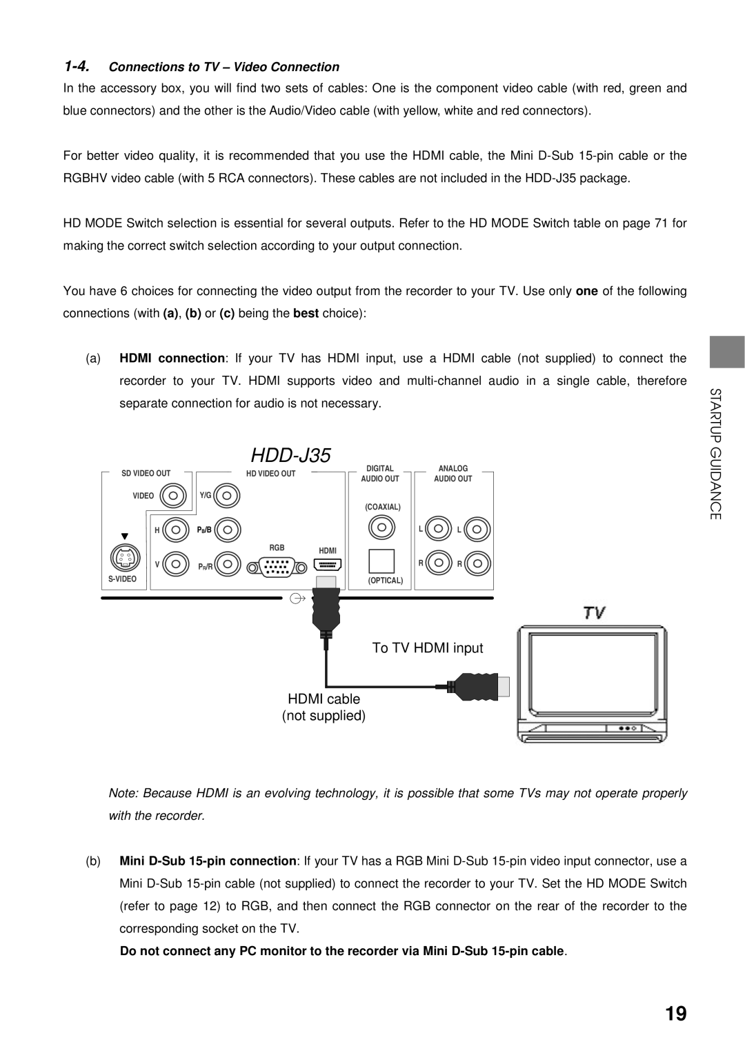
(a)HDMI connection: If your TV has HDMI input, use a HDMI cable (not supplied) to connect the recorder to your TV. HDMI supports video and
STARTUP
|
| |
SD VIDEO OUT | HD VIDEO OUT |
|
VIDEO | Y/G |
|
H | PB/B |
|
| RGB | HDMI |
|
| |
V | PR/R |
|
|
| |
DIGITAL
AUDIO OUT
(COAXIAL)
(OPTICAL)
ANALOG
AUDIO OUT
L ![]() L
L
R ![]() R
R
GUIDANCE
To TV HDMI input
HDMI cable
(not supplied)
Note: Because HDMI is an evolving technology, it is possible that some TVs may not operate properly with the recorder.
(b)Mini
Do not connect any PC monitor to the recorder via Mini
19