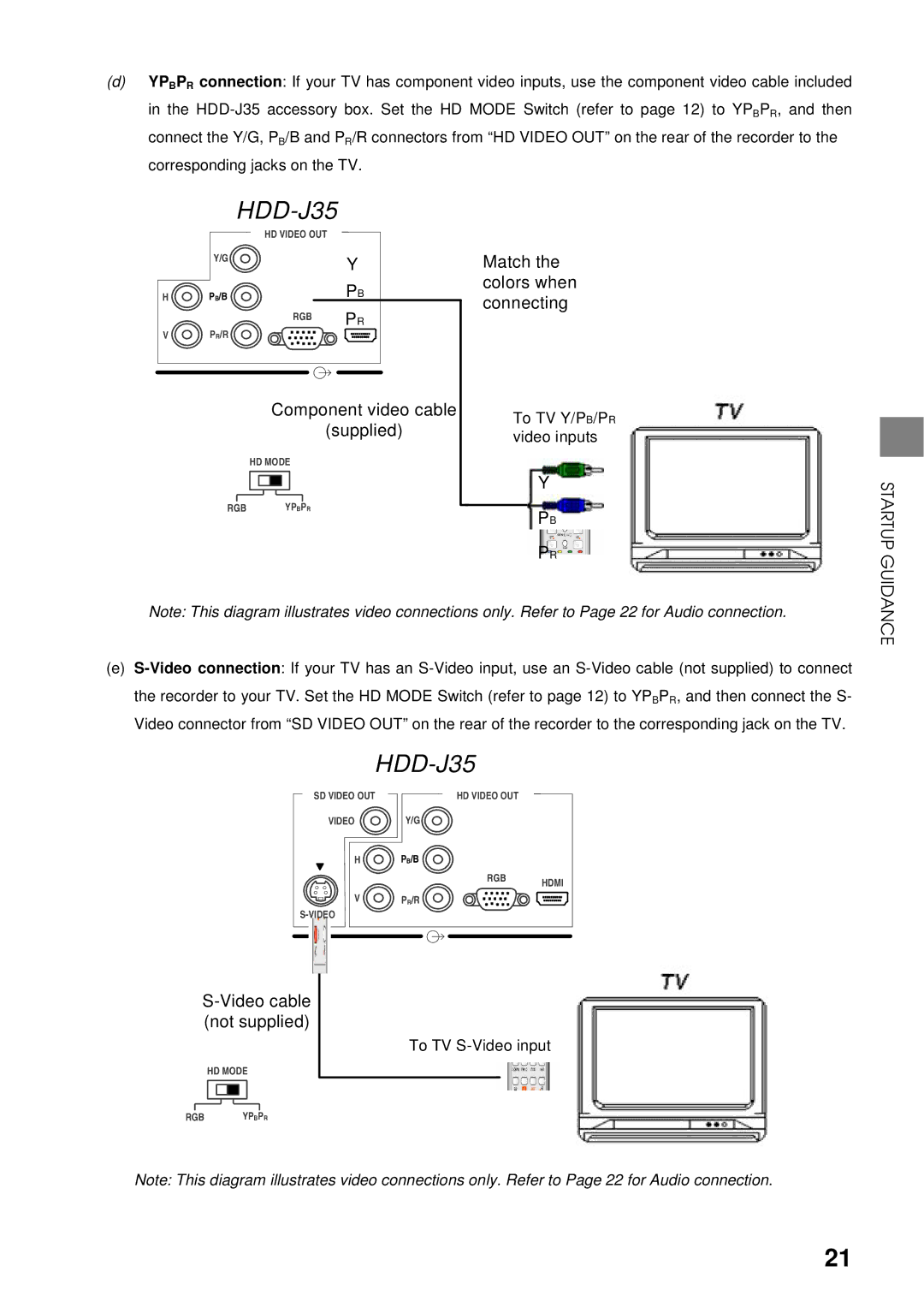
(d)YPBPR connection: If your TV has component video inputs, use the component video cable included in the
HDD-J35
HD VIDEO OUT
| Y/G |
| Y |
|
|
| |
H | PB/B |
| PB |
|
| RGB | HDMI |
V | PR/R |
| PR |
|
|
Component video cable
(supplied)
HD MODE
RGBYPBPR
Match the colors when connecting
To TV Y/PB/PR video inputs
Y
PB
PR
STARTUP GUIDANCE
Note: This diagram illustrates video connections only. Refer to Page 22 for Audio connection.
(e)
SD VIDEO OUT |
|
|
| HD VIDEO OUT |
VIDEO | Y/G |
|
H | PB/B |
|
| RGB | HDMI |
|
| |
V | PR/R |
|
|
|
S-Video cable (not supplied)
HD MODE
RGBYPBPR
To TV
Note: This diagram illustrates video connections only. Refer to Page 22 for Audio connection.
21