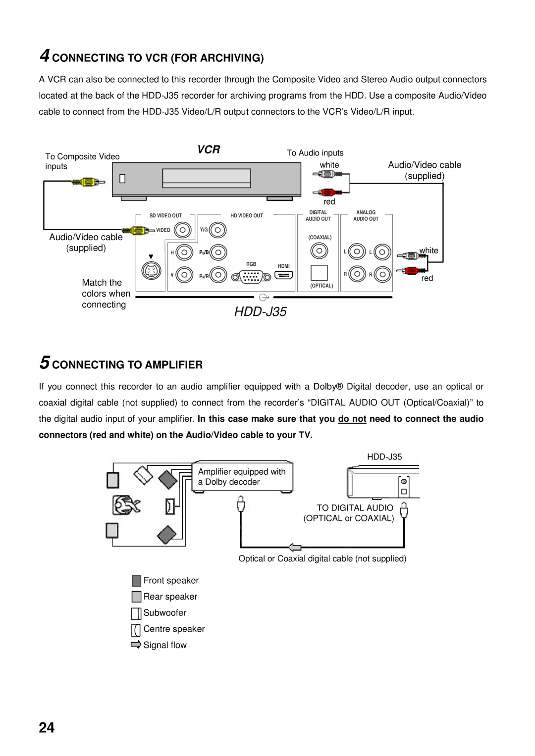
4 CONNECTING TO VCR (FOR ARCHIVING)
A VCR can also be connected to this recorder through the Composite Video and Stereo Audio output connectors located at the back of the
To Composite Video inputs
VCR | To Audio inputs |
| |||
|
|
|
| white | Audio/Video cable |
|
|
| |||
|
|
|
|
| (supplied) |
|
|
|
|
|
|
|
|
|
|
|
|
Audio/Video cable
(supplied)
Match the colors when connecting
|
|
| red |
|
|
SD VIDEO OUT | HD VIDEO OUT |
| DIGITAL |
| ANALOG |
| AUDIO OUT |
| AUDIO OUT | ||
|
|
|
| ||
VIDEO | Y/G |
|
|
|
|
|
|
| (COAXIAL) |
|
|
H | PB/B |
|
| L | L |
| RGB | HDMI |
|
|
|
|
|
|
|
| |
V | PR/R |
|
| R | R |
|
|
| (OPTICAL) |
|
|
|
|
|
|
| |
white
red
5 CONNECTING TO AMPLIFIER
If you connect this recorder to an audio amplifier equipped with a Dolby® Digital decoder, use an optical or coaxial digital cable (not supplied) to connect from the recorder’s “DIGITAL AUDIO OUT (Optical/Coaxial)” to the digital audio input of your amplifier. In this case make sure that you do not need to connect the audio
connectors (red and white) on the Audio/Video cable to your TV.
HDD-J35
Amplifier equipped with a Dolby decoder
TO DIGITAL AUDIO (OPTICAL or COAXIAL)
Optical or Coaxial digital cable (not supplied)
:Front speaker
:Rear speaker
![]()
![]() Subwoofer
Subwoofer
:Centre speaker
:Signal flow
24
