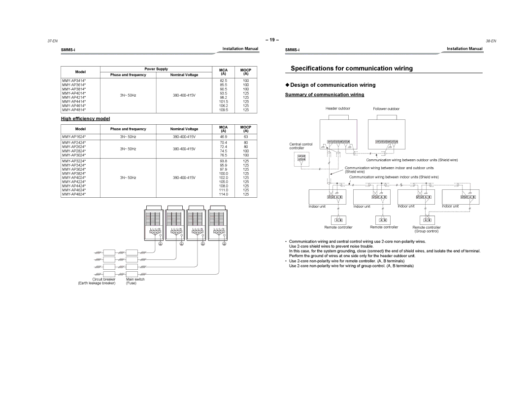
MMY-MAP0804HT8-E, MMY-MAP1604HT8Z-E, MMY-MAP1404HT8-E, MMY-MAP0804HT8Z-E, MMY-MAP1204HT8Z-E specifications
The Toshiba MMY-MAP0804HT8Z-E, MMY-MAP1404HT8-E, MMY-MAP1604HT8Z-E, MMY-MAP0804HT8-E, and MMY-MAP1604HT8-E are part of Toshiba's advanced air conditioning line-up, designed for both residential and commercial applications. These models are engineered to offer high efficiency, comfort, and reliability, making them an excellent choice for modern HVAC solutions.One of the standout features of these models is their high Seasonal Energy Efficiency Ratio (SEER), which indicates their superior energy performance. They are built to reduce energy consumption while providing optimal cooling and heating capabilities. This is particularly beneficial for users looking to lower their energy bills without sacrificing comfort.
In terms of technology, Toshiba incorporates inverter technology in these air conditioning units. The inverter system adjusts the compressor's speed according to the cooling demand, ensuring consistent temperatures and enhanced energy savings. This feature is especially useful during peak usage periods, as it minimizes energy spikes associated with traditional on/off systems.
Additionally, the MMY-MAP series includes sophisticated air filtration systems that improve indoor air quality. These filters capture dust, allergens, and other pollutants, creating a healthier living or working environment. The units also come equipped with a quiet operation mode, allowing them to function with minimal noise – a crucial aspect for residential settings and quiet commercial spaces.
These models boast a sleek and compact design, making them easy to install in various configurations. Their aesthetic appeal ensures they blend seamlessly with any interior decor. Furthermore, they are built to withstand diverse environmental conditions, with robust materials that ensure durability and longevity.
User-friendly controls are another hallmark of the Toshiba MMY-MAP series. Many of these models support smart technology, allowing for remote operation via smartphones or tablets. This capability enhances convenience, enabling users to monitor and adjust settings in real-time.
In summary, the Toshiba MMY-MAP0804HT8Z-E, MMY-MAP1404HT8-E, MMY-MAP1604HT8Z-E, MMY-MAP0804HT8-E, and MMY-MAP1604HT8-E models epitomize efficiency and comfort. With their energy-saving features, advanced inverter technology, effective air filtration, and smart connectivity, these air conditioning units are designed to meet the demands of modern users, ensuring a comfortable and healthy indoor environment all year round.

