– 9 – |
SMMS-i Installation Manual
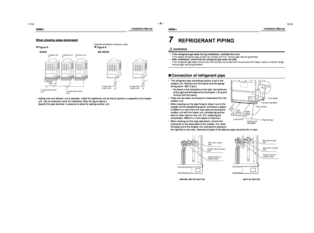
When drawing pipes downward
|
| [Vertical connection of branch units] |
▼ Figure 5 |
| ▼ Figure 6 |
GOOD |
| NO GOOD |
Header unit | Follower unit | Follower unit |
A | B | C |
|
| |
pipe |
|
|
| To | To |
To | branch unit | branch unit |
To |
| |
unit |
| |
| unit |
|
Installation Manual |
7 REFRIGERANT PIPING
![]() WARNING
WARNING
•If the refrigerant gas leaks during installation, ventilate the room.
If the leaked refrigerant gas comes into contact with fire, noxious gas may be generated.
•After installation, check that the refrigerant gas does not leak.
If the refrigerant gas leaks into the room and comes into contact with fire such as a fan heater, stove, or kitchen range, noxious gas may be generated.
Connection of refrigerant pipe
• The refrigerant pipe connecting section is set in the |
|
outdoor unit. Remove the front panel and the piping/ | Hook |
wiring panel. (M5: 9 pcs.) | |
• As shown in the illustration on the right, the hooks are |
|
at the right and left sides of the front panel. Lift up and |
|
•Adding only one follower unit is possible. Install the additional unit so that its position is opposite to the header unit. Use an extension valve for installation (See the figure above.).
Specify the pipe diameter in advance to allow for adding another unit.
remove the front panel. |
• | Pipes can be drawn out forward or downward from the |
|
|
| outdoor unit. |
|
|
• When drawing out the pipe forward, draw it out to the |
|
| |
| outside via the piping/wiring panel, and leave a space |
| 0 |
| of 500mm or more from the main pipe connecting the | 5 | |
|
| ||
| outdoor unit with the indoor unit, considering service |
|
|
| work or other work on the unit. (For replacing the |
|
|
| compressor, 500mm or more space is required.) |
|
|
• | When drawing out the pipe downward, remove the |
|
|
| knockouts on the base plate of the outdoor unit, draw |
|
|
| the pipes out of the outdoor unit, and perform piping on |
|
|
| the right/left or rear side. Downward length of the balance |
| |
|
|
|
|
|
|
| Front panel |
|
|
|
|
| o | r | Piping/wiring panel |
|
|
| m |
|
| ||
|
|
|
|
| (Rear piping) | ||
0 | m |
| e |
|
| ||
o | r |
|
|
| |||
m |
| (Left |
| ||||
|
|
|
| (Right | |||
|
|
|
|
| piping) | ||
Drawing out | piping) | ||||||
| |||||||
|
|
|
|
|
| forward | |
(Left piping) | Drawing out | (Right piping) |
| ||
|
| |
| downward |
|
pipe should be 5m or less.
| Ball valve of gas | |
Ball valve of gas | side | |
side |
| |
Packed valve of liquid | Ball valve of liquid | |
side | ||
side | ||
| ||
| Packed valve of | |
Packed valve of | balance pipe | |
balance pipe |
|
(MAP080, MAP100, MAP120) | (MAP140, MAP160) |