TL-WA5110G 54M High Power Wireless Access Point
1910010154
COPYRIGHT & TRADEMARKS
All rights reserved
FCC STATEMENT
FCC RF Radiation Exposure Statement
CE Mark Warning
General authorization required for outdoor use
and public service
National Restrictions 2400.0-2483.5 MHz
Country
Product Description 54 M High Power Wireless Access Point
ETSI EN 300 328 V1.7.1
ETSI EN 301 489-1 V1.8.12008 & ETSI EN 301 489-17 EN60950-12006
EN623112008
CONTENTS
Configuring the Device in AP Operation Mode
5.6.1
Package Contents
1.2 Features
Chapter 1. Product Overview
1.1 Overview of the Product
1.3 Conventions
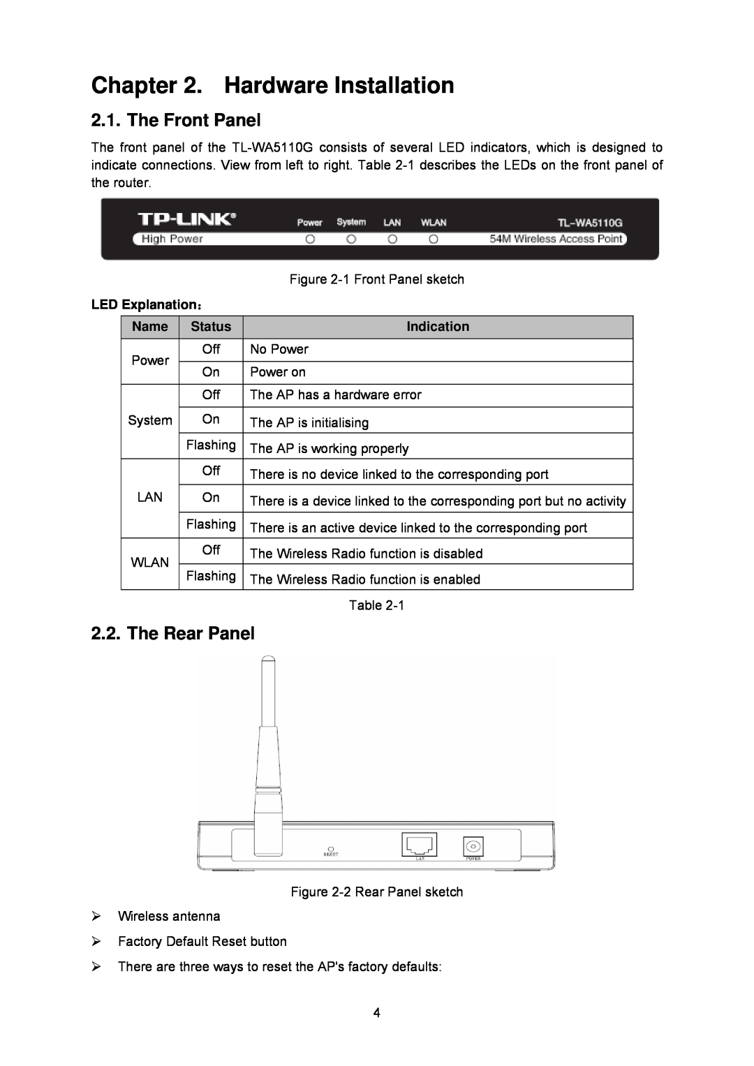
Chapter 2. Hardware Installation
2.1. The Front Panel
2.2. The Rear Panel
Indication
2.5. Connecting the Device
Ensure the AP is powered on before it restarts completely
2.3. System Requirements
2.4. Environment Requirements
3. Connect the AP to the desktop PC
Chapter 3. Quick Installation Guide
3.1. Configure the Device
For Windows 98 OS or earlier, the PC and AP may need to be restarted
3.2. Quick Setup
Please check the connection following these steps
Figure 3-4 Login Windows
Figure 3-7 Choose WAN Connection Type
The IP parameters should have been provided by your ISP
Figure 3-9 Quick Setup - Static IP
Figure 3-11 Quick Setup - Wireless settings
4.1 Login
4.2 Status
IP address and Subnet Mask 2. Wireless
SSID, Channel, Mode, Wireless MAC address, and IP address 3. WAN
1. LAN
4. Traffic Statistics
4.3 Quick Setup
4.4 Operation Mode
4.5 Network
4.5.1 LAN
4.5.2 WAN
Figure 4-5 WAN - Dynamic IP
Figure 4-6 WAN - Static IP
You should type the following parameters into the spaces provided
Figure 4-7 WAN - PPPoE
4.5.3 MAC Clone
4.6 Wireless
4.6.1 Basic Settings
1 Only the PC on your LAN can use the Clone MAC Address To feature
2 If you click Save, the router will prompt you to reboot
4.6.2 Wireless Mode
The device will reboot automatically after you click the Save button
Figure 4-12 Wireless Mode
Figure 4-13 AP List
4.6.3 Security Settings
Figure 4-14 Wireless Mode settings in AP Router mode
You can select one of the following security options
Figure 4-15 Wireless Security
2. Shared Key - Select 802.11 Shared Key authentication
3. Open System - Select 802.11 Open System authentication
¾ WEP - Select 802.11 WEP security
4.6.4 MAC Filtering
Figure 4-16 Wireless MAC address Filtering
¾ Status - The status of this entry either Enabled or Disabled
¾ Description - A simple description of the wireless station
To set up an entry, follow these instructions
6. Click the Save button to save this entry
4.6.5 Wireless Statistics
4.6.6 Distance Setting
This page will be refreshed automatically every 5 seconds
4.6.7 Antenna Alignment
4.6.8 Throughput Monitor
4.7.1 DHCP Settings
4.7 DHCP
4.7.2 DHCP Clients List
4.7.3 Address Reservation
To Reserve IP addresses
4.8 Wireless settings
4.9 Forwarding
4.9.1 Virtual Servers
To setup a virtual server entry, please take the following steps
4.9.2 Port Triggering
4.9.3 DMZ
4.9.4 UPnP
4.10Security
4.10.1 Firewall
4.10.2 IP Address Filtering
4.10.3 Domain Filtering
Click the Enabled All button to make all entries enabled
Figure 4-39 Domain Filtering
Figure 4-40 Add or Modify a Domain Filtering entry
To add or modify a Domain Filtering entry, follow these instructions
4.10.4 MAC Address Filtering
4.10.5 Advanced Security
Figure 4-43 Advanced Security settings
4.11Static Routing
To add static routing entries
4.12Dynamic DNS
4.12.1 Dyndns.org DDNS
4.12.2 Oray.net DDNS
4.12.3 Comexe.cn DDNS
4.13System Tools
4.13.1 Time
1. Select Using Daylight Saving Time
2 The router will reboot after the Upgrading is finished
4.13.2 Firmware
2 The time will be lost if the router is turned off
4.13.3 Factory Defaults
4.13.4 Backup & Restore
4.13.5 Ping Watch Dog
4.13.6 Speed Test
4.13.7 Reboot
4.13.8 Password
4.13.9 Syslog
4.13.10 Remote Management
4.13.11 Statistics
Statistics Table
Bytes
ICMP
TCP SYN Tx
Click the Refresh button to refresh immediately
Chapter 5. Configuring the Device in AP Operation Mode
5.1 Login
5.2 Status
5.3 Quick Setup
5.4 Operation Mode
5.5 Network
5.6 Wireless
5.6.1 Basic Settings
3) The device will reboot automatically after clicking Save
5.6.2 Wireless Mode
Page
If the available AP can’t support with WDS, you may select Client mode without WDS or Universal Repeater mode to associate with the AP
Figure 5-8 Point to Point Bridge
Page
5.6.3 Security Settings
the wireless network with wireless antenna accessories
Figure 5-11 Wireless Security
5.6.4 MAC Filtering
Figure 5-12 Wireless MAC address Filtering
Figure 5-13 Add or Modify Wireless MAC Address Filtering entry
6. Click the Save button to save this entry
5.6.5 Wireless Statistics
5.6.6 Distance Setting
5.6.7 Antenna Alignment
5.6.8 Throughput Monitor
5.7 DHCP
5.7.1 DHCP Settings
5.7.2 DHCP Clients List
5.7.3 Address Reservation
5.8 Wireless settings
5.9 System Tools
5.9.1 Firmware
5.9.2 Factory Defaults
5.9.3 Backup & Restore
5.9.4 Ping Watch Dog
5.9.5 Speed Test
2. Wrong process will lead the device unmanaged
Figure 5-29 Speed Test
5.9.6 Reboot
5.9.7 Password
5.9.8 Syslog
Click Save when finished Click Clear All to clear all
Figure 5-32 System Log
Click Clear ALL to clear all the logs
Appendix A FAQ
3. I want to use Netmeeting, what do I need to do?
4. I want to build a Web Server on the LAN, what should I do?
5. The wireless stations cannot connect to the router
Appendix B Configuring the PCs
1. Configure TCP/IP component
¾ Setting IP address automatically
Now you have two ways to configure the TCP/IP protocol below
¾ Setting IP address manually
Click OK to keep your settings
Appendix C Specifications
Wireless
General
Physical and Environment
Appendix D Glossary