Chapter 2 Using the Hardware
Using the GPIO Interface
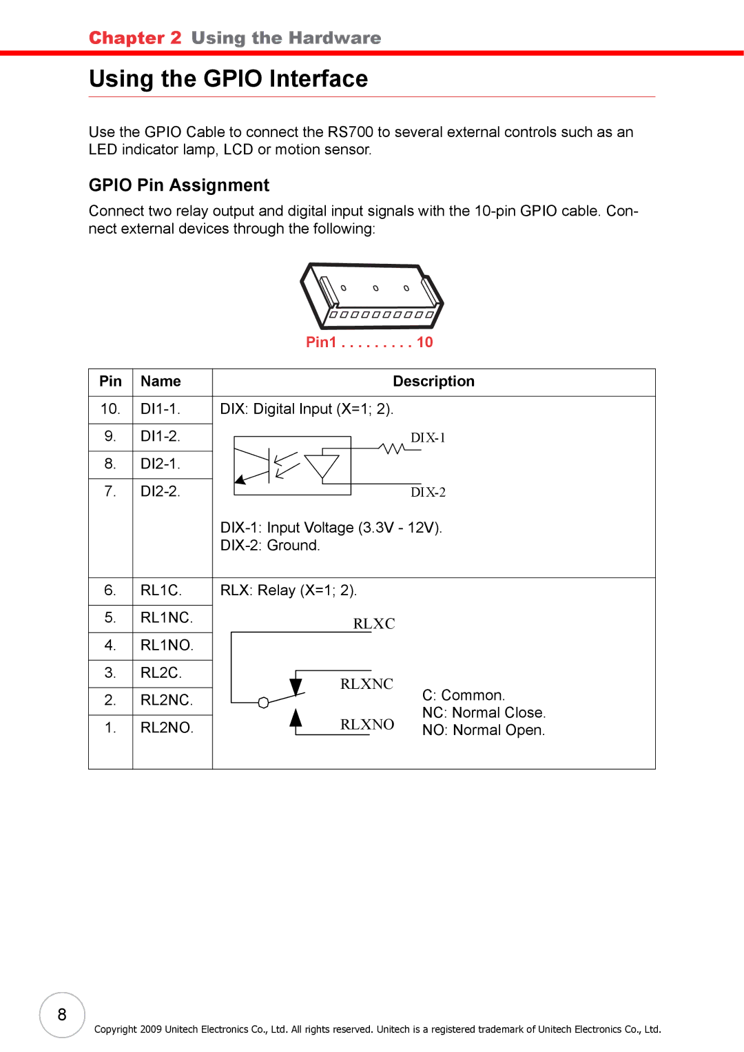
Use the GPIO Cable to connect the RS700 to several external controls such as an LED indicator lamp, LCD or motion sensor.
GPIO Pin Assignment
Connect two relay output and digital input signals with the
Pin1 . . . . . . . . . 10
Pin Name | Description |
10.
9. |
| |||
8. |
|
| ||
7. |
| |||
|
| |||
|
|
| ||
6. | RL1C. | RLX: Relay (X=1; 2). |
| |
5. | RL1NC. | RLXC |
| |
|
|
| ||
4. | RL1NO. |
|
| |
3. | RL2C. | RLXNC |
| |
2. | RL2NC. | C: Common. | ||
| ||||
1. | RL2NO. | RLXNO | NC: Normal Close. | |
NO: Normal Open. | ||||
8
Copyright 2009 Unitech Electronics Co., Ltd. All rights reserved. Unitech is a registered trademark of Unitech Electronics Co., Ltd.