Direct Vent Models DVRT36 DVRT39 DVRT43
Homeowners Installation
Vermont Castings, Majestic Products
INSTALLER/CONSUMER SAFETY INFORMATION
Vermont Castings, Majestic Products DVRT36/39/43
Table of Contents
Installation & Operating Instructions
Venting Installation Instructions
Locating the Fireplace
Installation & Operating Instructions
Vermont Castings, Majestic Products DVRT36/39/43
10002428
Framing Dimensions
Fireplace Dimensions Installed as Top Vent
Vermont Castings, Majestic Products DVRT36/39/43
DVRT36
Fireplace Dimensions Installed as Rear Vent
Vermont Castings, Majestic Products DVRT36/39/43
10002428
Mantels
Clearance to Combustibles
Hearth
Vermont Castings, Majestic Products DVRT36/39/43
Framing & Finishing
Gas Specifications
Final Finishing
Gas Inlet and Manifold Pressures
Remote ON/ OFF Switch Installation
Gas Line Installation
Alternate Switch Location
Vermont Castings, Majestic Products DVRT36/39/43
Electronic Gas Control Valve
EB-1Electrical Box
Vermont Castings, Majestic Products DVRT36/39/43
10002428
Optional Top Vent Application
Installing the DVRT36RMH in a Mobile Home
Vermont Castings, Majestic Products DVRT36/39/43
10002428
General Venting
Vermont Castings, Majestic Products DVRT36/39/43
10002428
US Installations2
Canadian Installations1
Vermont Castings, Majestic Products DVRT36/39/43
10002428
Crimped End Pipes
General Information for Connecting Vent Pipes
Vermont Castings, Majestic Products DVRT36/39/43
10002428
Twist-lockPipes
How to Use the Vent Graph
Rear Wall Vent Application
Vermont Castings, Majestic Products DVRT36/39/43
Vermont Castings, Majestic Products DVRT36/39/43
Rear Wall Vent Installation
Step
Step
Vertical Sidewall Application
Vermont Castings, Majestic Products DVRT36/39/43
10002428
Vertical Sidewall Installation
Vermont Castings, Majestic Products DVRT36/39/43
10002428
Below Grade Installation
Vermont Castings, Majestic Products DVRT36/39/43
10002428
Vermont Castings, Majestic Products DVRT36/39/43
Vertical Through-the-RoofApplication
Do not backfill around snorkel
10002428
Vertical Through-the-RoofInstallation
Vermont Castings, Majestic Products DVRT36/39/43
10002428
Vermont Castings, Majestic Products DVRT36/39/43
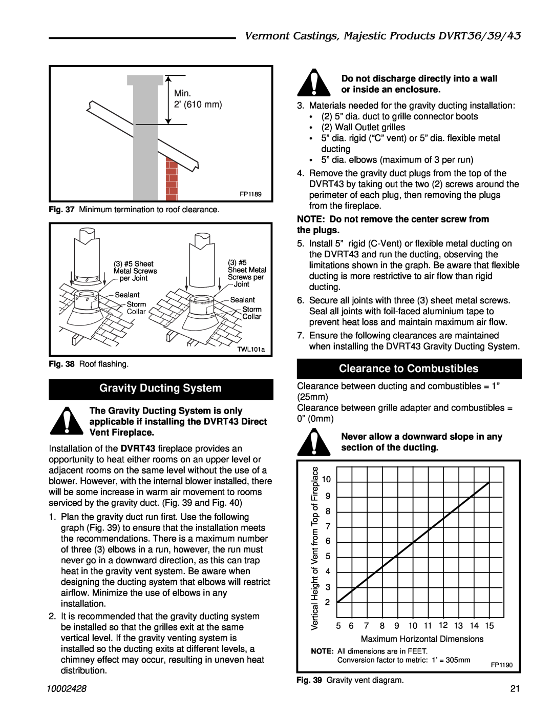
Gravity Ducting System
Clearance to Combustibles
Min 2’ 610 mm
Sheet Metal
Vermont Castings, Majestic Products DVRT36/39/43
Gravity
Screws
Twist Lock Venting Components
Vermont Castings, Majestic Products DVRT36/39/43
10002428
Crimped End Venting Components
Vermont Castings, Majestic Products DVRT36/39/43
10002428
Glass Cleaning
Window Frame Assembly Removal
Operating Instructions
Glass Information
Installation of Logs & Lava Rock
Vermont Castings, Majestic Products DVRT36/39/43
10002428
Flame Characteristics
Flame & Temperature Adjustment
Vermont Castings, Majestic Products DVRT36/39/43
10002428
Inspecting the Venting System
Vermont Castings, Majestic Products DVRT36/39/43
10002428
Lighting & Operating Instructions
FOR YOUR SAFETY, READ BEFORE LIGHTING
Lighting Instructions
To Turn Off Gas to Heater
before Lighting the Appliance
For Your Safety, Read the Following Warnings
Turning Off the Gas to the Appliance
Vermont Castings, Majestic Products DVRT36/39/43
Instructions for RF Comfort Control Valve
Shutoff Procedure
Operation of RF Comfort Control Valve
Transmitter Operation
Troubleshooting RF Comfort Control Valve
Disable Thermostat Function
Delay Time Mode
Auto Mode
Vermont Castings, Majestic Products DVRT36/39/43
Auto Path Chart
Auto Path
10002428
10002428
Vermont Castings, Majestic Products DVRT36/39/43
LOCAL to RE
LOCAL
Troubleshooting - Honeywell VS8421
Vermont Castings, Majestic Products DVRT36/39/43
10002428
SYMPTOM
Troubleshooting the Gas Control System
Vermont Castings, Majestic Products DVRT36/39/43
SIT NOVA 820 MILLIVOLT VALVE
Vermont Castings, Majestic Products DVRT36/39/43
Troubleshooting the Gas Control System
SIT 822 Valve with a Honeywell Electronic Igniter
START
Fuel Conversion Instructions
Vermont Castings, Majestic Products DVRT36/39/43
10002428
Cleaning the Standing Pilot Control System
Maintenance
Vermont Castings, Majestic Products DVRT36/39/43
10002428
Vermont Castings, Majestic Products DVRT36/39/43
DVRT36/39/43
10002428
DVRT43
Description
Vermont Castings, Majestic Products DVRT36/39/43
DVRT36
DVRT39
DVRT36/39/43 continued
Vermont Castings, Majestic Products DVRT36/39/43
10002428
Hard Direct Wire Hookup
Optional Accessories
Fan Kits
Vermont Castings, Majestic Products DVRT36/39/43
Ceramic Refractory Panels
Remote Controls
Decorative Bay Window
Vermont Castings, Majestic Products DVRT36/39/43
Vermont Castings, Majestic Products DVRT36/39/43
Decorative Frame Trim
10002428
Fig. 62 Bay window
Conversion Instructions
For Use in Mobile Homes Model DVRT36RMH
Vermont Castings, Majestic Products DVRT36/39/43
10002428
Vermont Castings, Majestic Products DVRT36/39/43
9b.Units with Honeywell valve
10002428
PRODUCT COVERED BY THIS WARRANTY
LIMITED LIFETIME WARRANTY
IF WARRANTY SERVICE IS NEEDED…
Vermont Castings, Majestic Products DVRT36/39/43
10002428
Vermont Castings, Majestic Products DVRT36/39/43
Vermont Castings, Majestic Products
Efficiency Ratings
Model
EnerGuide Ratings