APPENDIX (A)
Relays In General
NOTE: Viking Access Systems does not provide the external safety devices and access controls. These items can be purchases from your dealer or distributor.
In General
In regards to the Viking control board, all external safety devices and access controls contain, and are, simple relays that provide an input to the Viking control board when the device is activated.
When these devices are activated, their internal relays create a contact, or short, between the “C” and “N.O.” terminals. This contact is what provides the command to the Viking control board.
!TECHNICAL TIP: Viking uses the
Normally Open “N.O.” contact from the device, excluding
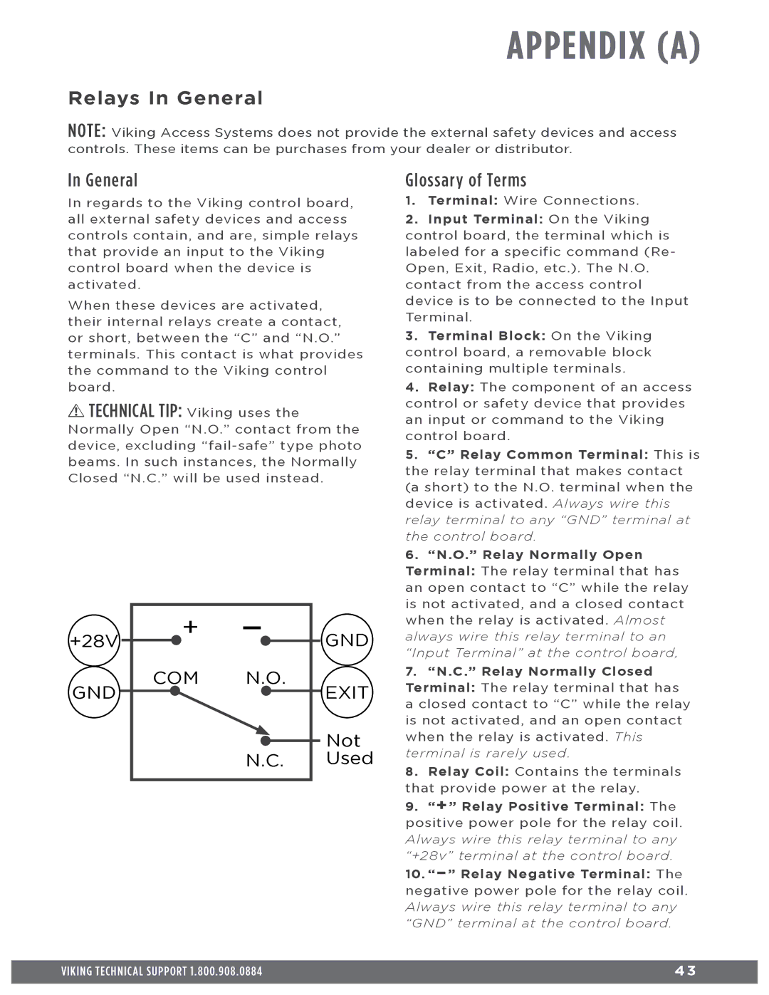
+28V | + | — | GND |
|
| ||
GND | COM | N.O. | EXIT |
|
| ||
|
|
| Not |
|
| N.C. Used | |
Glossary of Terms
1.Terminal: Wire Connections.
2. Input Terminal: On the Viking control board, the terminal which is labeled for a specific command (Re- Open, Exit, Radio, etc.). The N.O. contact from the access control device is to be connected to the Input Terminal.
3.Terminal Block: On the Viking control board, a removable block containing multiple terminals.
4.Relay: The component of an access control or safety device that provides an input or command to the Viking control board.
5.“C” Relay Common Terminal: This is the relay terminal that makes contact (a short) to the N.O. terminal when the device is activated. Always wire this relay terminal to any “GND” terminal at the control board.
6.“N.O.” Relay Normally Open Terminal: The relay terminal that has an open contact to “C” while the relay is not activated, and a closed contact when the relay is activated. Almost always wire this relay terminal to an “Input Terminal” at the control board,
7.“N.C.” Relay Normally Closed Terminal: The relay terminal that has a closed contact to “C” while the relay is not activated, and an open contact when the relay is activated. This terminal is rarely used.
8.Relay Coil: Contains the terminals that provide power at the relay.
9.“+” Relay Positive Terminal: The positive power pole for the relay coil. Always wire this relay terminal to any “+28v” terminal at the control board.
10.
VIKING TECHNICAL SUPPORT 1.800.908.0884 | 4 3 |
|
|