ACCESSORY CONNECTIONS
Guidelines for Loop Installation
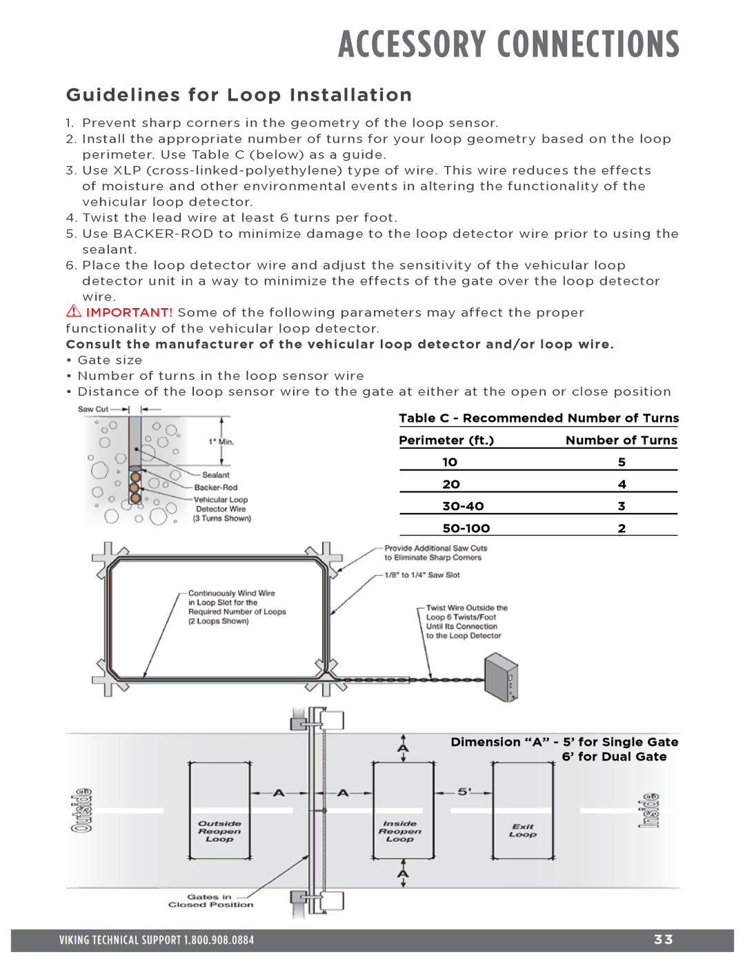
1. Prevent sharp corners in the geometry of the loop sensor.
2. Install the appropriate number of turns for your loop geometry based on the loop perimeter. Use Table C (below) as a guide.
3. Use XLP
4. Twist the lead wire at least 6 turns per foot.
5. Use
6. Place the loop detector wire and adjust the sensitivity of the vehicular loop detector unit in a way to minimize the effects of the gate over the loop detector wire.
! IMPORTANT! Some of the following parameters may affect the proper functionality of the vehicular loop detector.
Consult the manufacturer of the vehicular loop detector and/or loop wire.
• Gate size
• Number of turns in the loop sensor wire
• Distance of the loop sensor wire to the gate at either at the open or close position
Table C - Recommended Number of Turns
Perimeter (ft.) | Number of Turns | |
| 10 | 5 |
| 20 | 4 |
| 3 | |
| 2 | |
Dimension “A” - 5’ for Single Gate 6’ for Dual Gate
VIKING TECHNICAL SUPPORT 1.800.908.0884 | 3 3 |
|
|