CONTROL BOARD REFERENCES:
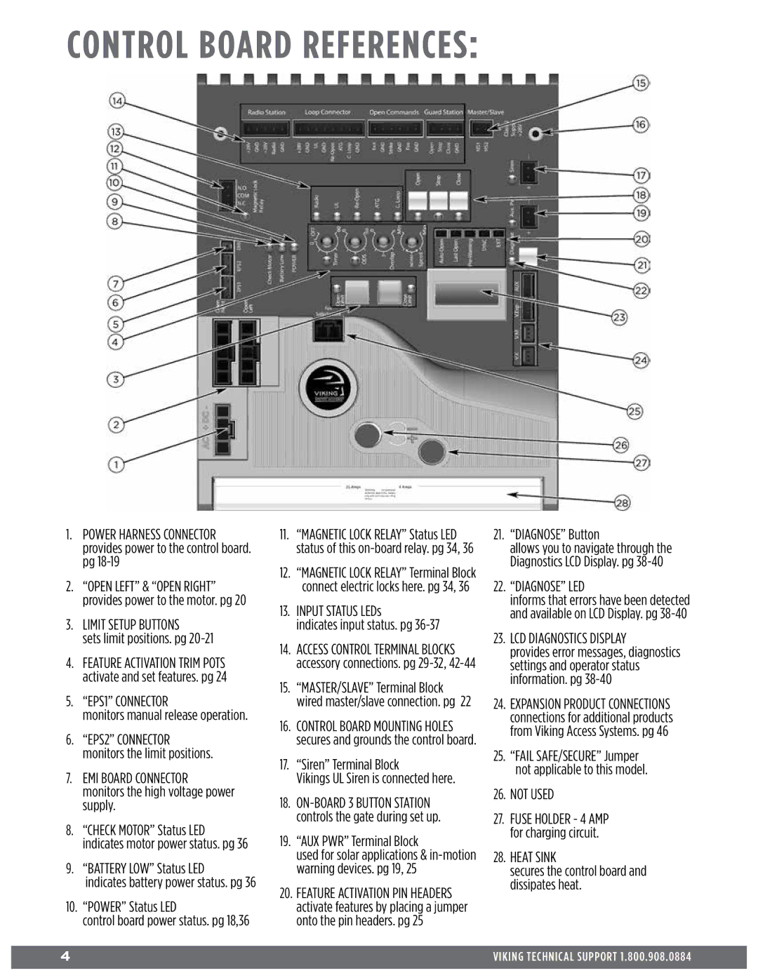
1.POWER HARNESS CONNECTOR provides power to the control board. pg
2.“OPEN LEFT” & “OPEN RIGHT” provides power to the motor. pg 20
3.LIMIT SETUP BUTTONS
sets limit positions. pg
4.FEATURE ACTIVATION TRIM POTS activate and set features. pg 24
5.“EPS1” CONNECTOR
monitors manual release operation.
6.“EPS2” CONNECTOR monitors the limit positions.
7.EMI BOARD CONNECTOR
monitors the high voltage power supply.
8.“CHECK MOTOR” Status LED indicates motor power status. pg 36
9.“BATTERY LOW” Status LED
indicates battery power status. pg 36
10.“POWER” Status LED
control board power status. pg 18,36
11.“MAGNETIC LOCK RELAY” Status LED status of this
12.“MAGNETIC LOCK RELAY” Terminal Block connect electric locks here. pg 34, 36
13.INPUT STATUS LEDs
indicates input status. pg 36-37
14.ACCESS CONTROL TERMINAL BLOCKS accessory connections. pg
15.“MASTER/SLAVE” Terminal Block wired master/slave connection. pg 22
16.CONTROL BOARD MOUNTING HOLES secures and grounds the control board.
17.“Siren” Terminal Block
Vikings UL Siren is connected here.
18.
19.“AUX PWR” Terminal Block
used for solar applications &
20.FEATURE ACTIVATION PIN HEADERS activate features by placing a jumper onto the pin headers. pg 25
21.“DIAGNOSE” Button
allows you to navigate through the Diagnostics LCD Display. pg
22.“DIAGNOSE” LED
informs that errors have been detected and available on LCD Display. pg
23.LCD DIAGNOSTICS DISPLAY
provides error messages, diagnostics settings and operator status information. pg
24.EXPANSION PRODUCT CONNECTIONS connections for additional products from Viking Access Systems. pg 46
25.“FAIL SAFE/SECURE” Jumper
not applicable to this model.
26.NOT USED
27.FUSE HOLDER - 4 AMP for charging circuit.
28.HEAT SINK
secures the control board and dissipates heat.
4 | VIKING TECHNICAL SUPPORT 1.800.908.0884 |
|
|