DVR-920H
Class Laser Product
Operating Environment
Ventilation Caution
Contents
Initial Setup menu
Disc Setup menu
Video/Audio Adjust menu
Copying and back-up
Features
Before you start
Before you start Chapter
Chapter marking VR mode
Before you start
Before you start What’s in the box
Use within the operating range and angle, as shown
CD-R/RW compatibility
General disc compatibility
DVD-R/RW compatibility
Compressed audio compatibility
Jpeg file compatibility
Frequently asked questions
WMA Windows Media Audio compatibility
PC-created disc compatibility
About the internal hard disk drive
Optimizing HDD performance
Rear panel connections
Connecting up
Connecting up Chapter
Front panel connections
Connecting up Extra features for use with compatible TVs
Connecting up Easy connections
Using the S-video or component video output
Connecting up Using other types of audio/video output
Using the supplied audio/video cable
Connect the Video Output jack to a video input on your TV
This enables you to record scrambled TV channels
This enables you to watch and record TV channels
This enables you to watch discs
Plug the supplied G-LINK cable to the G-LINK jack
Connecting up Connecting an external decoder box
Antenna
Connecting up Connecting to an AV amplifier/receiver
This enables you to listen to multichannel surround sound
Connecting up Connecting using Hdmi
About Hdmi
Connecting a DV camcorder
Connecting up Connecting other AV sources
Connecting a VCR or analog camcorder
Plugging
Controls and displays
Controls and displays Chapter
Front panel
Return
Controls and displays
Display
REM
Remote control
Ntsc
Pause
REV Scan / FWD Scan
Play
Stop
Getting started Chapter
Switching on and setting up
Getting started
Enter
Getting started
Is your TV compatible with progressive scan video?
Other settings you can make
Select the TV screen type, ‘Wide 169’ or ‘Standard 43’
Compatible, Not Compatible, or Don’t Know, then press Enter
Use Cursor up/down buttons to select Postal Code
Getting started Setting up the Guide Plus+ system
Press Guide to display the Guide Plus+ setup menu
Use the number and cursor buttons to enter your postal code
About EPG download
Identify the host channel for your country
Country Host channels Comments Region
Selecting the hard disk or DVD for playback and recording
Checking the downloaded data the following day
Press Guide
Playing back your recording
When you want to stop recording, press
Getting started Making your first recording
Press REC to start recording
Changing TV channels
Getting started Using the built-in TV tuner
Switching between TV and DVD
Changing audio channels
To stop playback, press Stop
Press STANDBY/ON to switch on
Getting started Basic playback
Press HDD to playback from the HDD, or DVD to play a DVD
Playing DVD discs
Playing from the HDD
Playing CDs and WMA/MP3 discs
Playing Video CD/Super VCDs
Getting started Using the Home Menu
Displaying disc information on- screen
Home menu options
HDD and removable disc activity display
Stop display
Play display
Recording display3
Using Guide Plus+
Using the Guide Plus+ electronic program guide
Using the Guide Plus+ electronic program guide Chapter
Guide Plus+ System
Using the Guide Plus+ electronic program guide
Navigating Guide Plus+
One-Button-Record
Channel mosaic screen
Areas
Lock / Unlock video window
Grid Area
Browsing the Grid
Using My Choice keywords for a search
Search Area
Searching
Channels is now highlighted
Setting up a profile
My TV Area
Press Enter to activate your profile
Schedule Area
Editing a scheduled recording
Press cursor right to access the extended recording options
Deleting a scheduled recording
Setting a Video Plus* recording Setting a manual recording
Select ‘Schedule’ from the Menu bar
Press Enter to confirm
Editor Area
Switching a channel on/off
Info Area
Changing the source and program number
Making changes to your Guide Plus+ setup
Guide Plus+ FAQ and troubleshooting
Setup Area
FAQ
TV listings information doesn’t update
Playback Chapter
Using the Disc Navigator to browse the contents of a disc
Playback
Introduction
Using the Disc Navigator with recordable discs and the HDD
Playback
Changing the thumbnail picture for a title
Optionally Press Enter
Navigating discs and the HDD
Scanning discs
Scanning speed is shown on-screen
Slow 1/2
Playing in slow motion
Frame advance/frame reverse
Scan 11 Scan 2 Scan 3 Scan
Playback Play Mode menu
Search Mode
Play Mode
Program play
Select ‘Program’ from the Play Mode menu
Repeat
Repeat play
Other Program play functions
Repeat to build up a program list
Select a program play function Input/Edit Program See above
Press Subtitle repeatedly to select a subtitle option
Switching audio channels
To switch off subtitles, press Subtitle then
Press Audio repeatedly to select an audio soundtrack
Stereo Stereo default Left channel only Right channel only
Switching camera angles
To display/switch the audio channel, press Audio repeatedly
Audio channels currently playing are indicated on- screen
About DVD recording
Recording
Recording Chapter
Recording time and picture quality
Restrictions on video recording
Setting the picture quality/recording time
Recording
Recording equipment and copyright
Basic recording from the TV
Press REC Mode repeatedly to select a recording setting
Front panel display shows the channel preset number or name
Use the Audio button to select the audio channel to record
Setting a timer recording
Direct recording from TV
Easy Timer Recording
Press Home Menu and select Easy Timer
Extending a timer recording in progress
Moving the end time by 30-minute blocks
MON 13/12
When you want to stop recording completely, press Stop REC
Timer recording FAQ
Canceling and stopping a timer recording in progress
You can’t enter a timer program if the clock isn’t set
Press REC when you’re ready to start recording
See Connecting up for connection options
Set up the recorder
Recording from an external component
Also, set the camcorder to VTR mode
Recording Recording from a DV camcorder
Finalizing a disc
Recording from the DV output
Playing your recordings on other DVD players
Use
Press Home Menu and select ‘Disc Setup’ Select ‘Initialize’
Initializing a DVD-RW disc
It takes about 30 seconds to initialize the disc
Copying and back-up
Copying and back-up Chapter
High-speed copying
Copying and back-up
One Touch Copy1 HDD to DVD
Canceling One Touch Copy
Copying and back-up One Touch Copy1 DVD to HDD
Copying from HDD to DVD3
HDD to DVD Copy List menu options
Select ‘HDD DVD’
HDD to DVD Copy List screen appears
Recording the Copy List
HDD to DVD Copy List commands
Select ‘Conf List’ to display the Copy List settings screen
Add
Divide
Erase
Title Name Ttl Name
Select ‘Erase’ from the Copy List menu options
Move
Preview
Combine
English
Select a command from the chapter edit menu options
Erase All
Chapter Edit Chpt Edit
Chapter Edit Combine
Chapter Edit Divide
Chapter Edit Move
Use Cursor buttons to select a
Erase Section Erase Sec
Copying and back-up Copying from DVD to HDD1
Currently selected DVD title
DVD to HDD Copy screen appears
DVD to HDD Copy List menu options
Select ‘DVD
Use Cursor up/down buttons to highlight
Copying and back-up DVD to HDD Copy List commands
Use this command to add titles to the Copy List.1
Title to move Copy List insertion point
Using disc back-up1
Read from disc and save to HDD Start reading? Start Cancel
Editing
Editing Chapter
Disc Navigator screen
HDD Disc Navigator
New indicator
Editing
HDD group tabs
VR mode Original
Playlist / Original indicator
Playback will automatically stop when you do this
Disc Navigator menu options
Erase Section Erase Sec Erase a part of a title
Editing VR mode Original, Video mode and HDD content
Play
Use this function to start playback of a title
Using the remote key shortcuts to input a name
Key Characters
Inserting chapter markers into a title
Lock / Unlock
Select ‘Erase Sec’ from the Disc Navigator menu options Use
Title
Change Group Chg Group
Editing HDD groups
Undo
Select the title that you want to divide, then press Enter
Group Name Grp Name
Creating and editing a VR mode Play List
Use this command to rename a group
Input a name for the group
Select the title you want to erase, then press
You can give titles new names of up to 64 characters long
Select ‘Ttl Name’ from the Disc Navigator Play
Create
New title appears in the updated Play List
Original title to put into the Play List
Press Enter to add the title
Select the title that you want to divide, then
Select ‘Divide’ from the Disc Navigator Play List
Menu options
Press Enter
Using the Disc History
Disc History
Disc History Chapter
Playing a slideshow
PhotoViewer
PhotoViewer Chapter
Reloading files from a disc
PhotoViewer
Zooming the screen
Rotating the screen
Basic settings
Disc Setup menu
Disc Setup menu Chapter
Input Disc Name
Disc Setup menu Initialize settings
Finalize settings
Setting the picture quality for TV and external inputs
Video/Audio Adjust menu
Video/Audio Adjust menu Chapter
Choosing a preset
Video/Audio Adjust menu
Setting the picture quality for disc playback
Select the picture quality setting you want to adjust
Audio DRC
DRC from ‘Off‘ to ‘Max’
Using the Initial Setup menu
Initial Setup menu
Initial Setup menu Chapter
Clock Setting
Input Line System
Initial Setup menu
Power Save
Front Panel Display
Setup Navigator
Tuner settings
Remote Control Mode
Auto Channel Setting Auto Scan
Auto Channel Setting Download from TV
Manual CH Setting
Video In / Out settings
Channel Swapping
Input Colour System
Input Line System Built-in tuner External input
Component Video Out
AV1 Out
PAL Secam
Ntsc on PAL TV Nicam Select
Audio In settings
AV2/L1
Tuner Level
Audio Out settings
Language settings
Subtitle Language
Default setting w/Subtitle Language
Default setting On
DVD Menu Language
Manual Recording
Recording settings
Selecting ‘Other’ languages
Optimized Rec
Playback settings
Still Picture
Parental Lock Set Password
Parental Lock Change Password
Seamless Playback
Parental Lock Change Level
Parental Lock Country Code
Hdmi Output
HDCP-compatible DVI device
About Hdmi Output default settings
HDMI-compatible device
Aspect Progressive Full Colour RGB Full Range
Using the TV remote control buttons
Resetting the recorder
Setting up the remote to control your
Additional information
When viewing on a standard TV or monitor
When viewing on a widescreen TV or monitor
Additional information Screen sizes and disc formats
General
Additional information Troubleshooting
Problem Remedy
Disc Navigator
Additional information
Front panel display shows ‘LOCK’
When a button is pressed Can’t use One Touch Copy HDD to
Panel and remote control buttons
Picture freezes and the front
Additional information Frequently asked questions
How do I make a high-quality copy?
Additional information About DV
DV-related messages
Video mode
Additional information Manual recording modes
Level
Language Language code letter, Language code
Additional information Language code list
Country code list
Country, Country code, Country code letter
Message
Handling discs
Storing discs
Message Explanation/Action
Additional information Damaged discs
Cleaning the pickup lens
Hints on installation
Condensation
Additional information Glossary
Optical digital output
Mpeg audio
Mpeg video
PCM Pulse Code Modulation
Tuner
Additional information Specifications
Timer
Input/Output
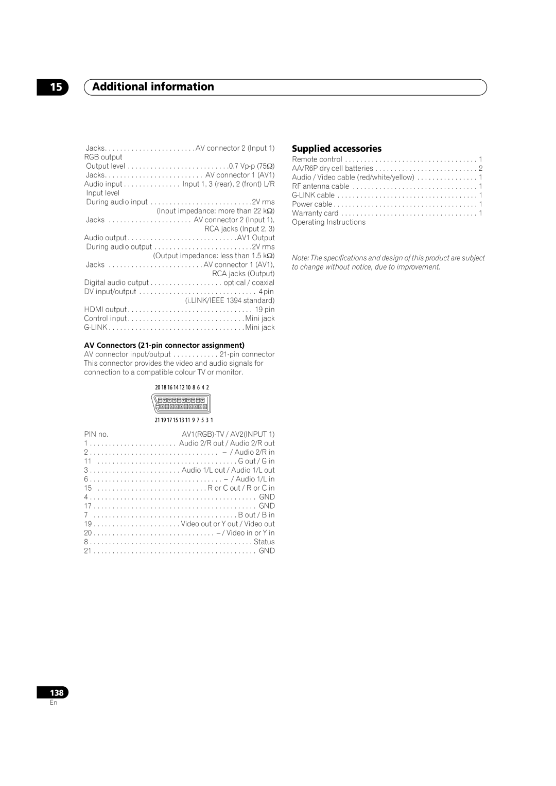
PIN no
Supplied accessories
AV Connectors 21-pin connector assignment
Audio 2/R out / Audio 2/R out
Index
Index
BOX 1540, Long Beach, California 90810-1540, U.S.A. TEL 800
Allstate Parkway, Markham, Ontario L3R OP2, Canada TEL
VRB1352-A