VIVOTEK
Physical Description
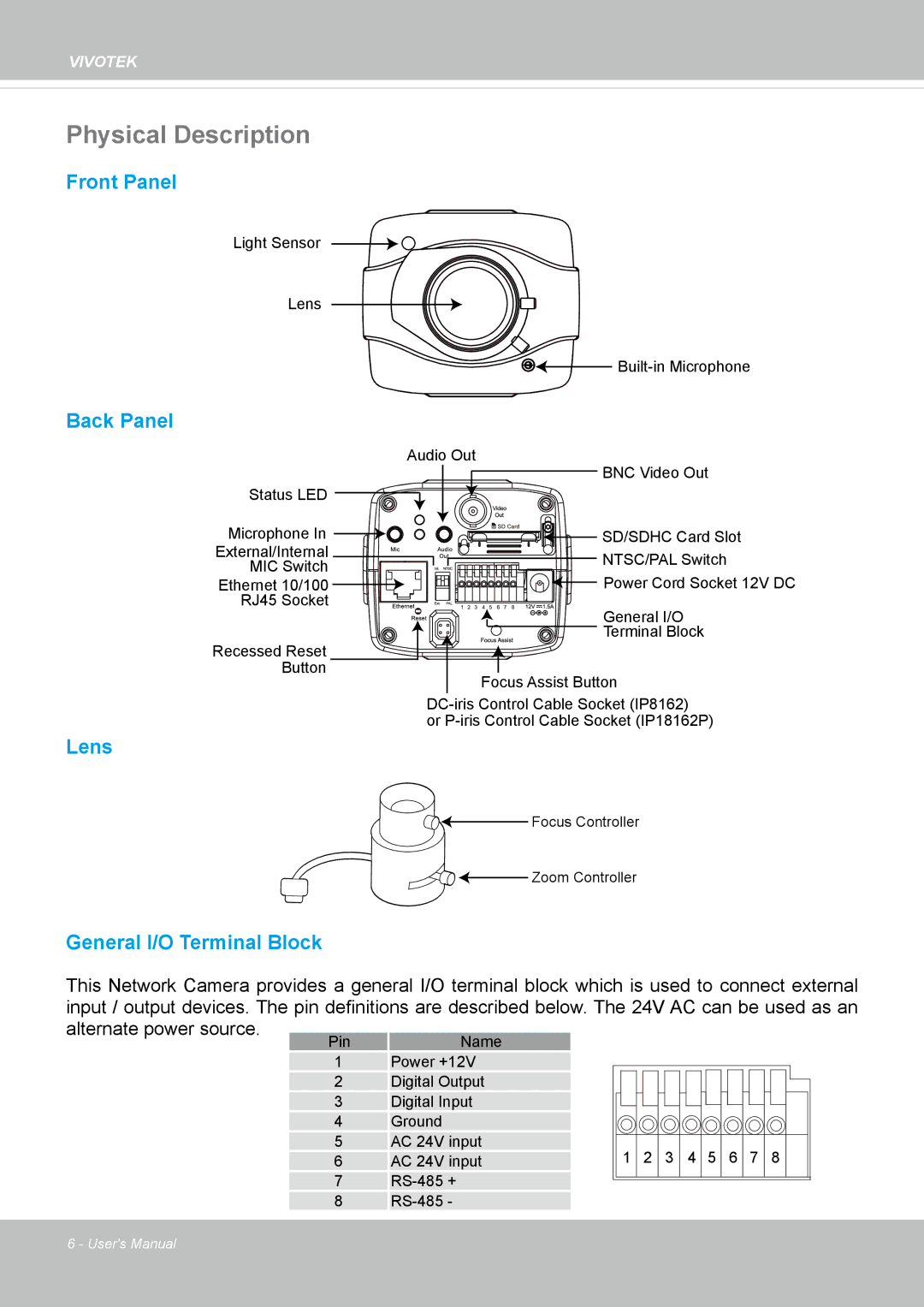
Front Panel
Light Sensor
Lens
![]()
![]()
Back Panel
| Audio Out | |
| BNC Video Out | |
Status LED |
| |
Microphone In | SD/SDHC Card Slot | |
External/Internal | NTSC/PAL Switch | |
MIC Switch | ||
Power Cord Socket 12V DC | ||
Ethernet 10/100 | ||
RJ45 Socket |
|
General I/O |
Terminal Block |
Recessed Reset |
Button |
Focus Assist Button |
or
Lens
![]() Focus Controller
Focus Controller
![]()
![]()
![]() Zoom Controller
Zoom Controller
General I/O Terminal Block
This Network Camera provides a general I/O terminal block which is used to connect external input / output devices. The pin definitions are described below. The 24V AC can be used as an
alternate power source. | Pin | Name |
|
|
| ||
| 1 | Power +12V |
|
| 2 | Digital Output |
|
| 3 | Digital Input |
|
| 4 | Ground |
|
| 5 | AC 24V input | 1 2 3 4 5 6 7 8 |
| 6 | AC 24V input | |
| 7 |
| |
| 8 |
|
6 - User's Manual