VIVOTEK
Network Deployment
Setting up the Network Camera over the Internet
This section explains how to configure the Network Camera to an Internet connection.
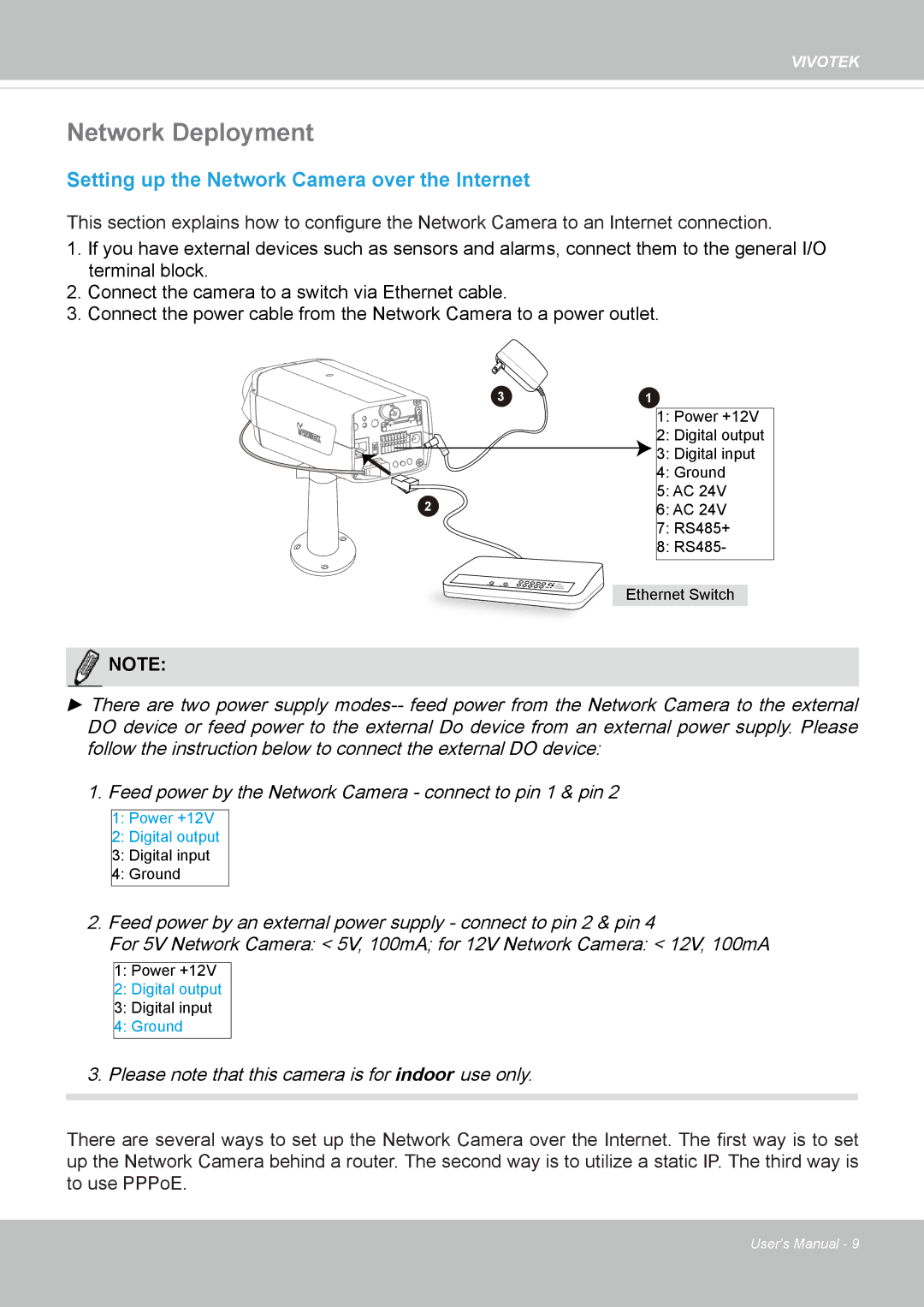
1.If you have external devices such as sensors and alarms, connect them to the general I/O terminal block.
2.Connect the camera to a switch via Ethernet cable.
3.Connect the power cable from the Network Camera to a power outlet.
3 | 1 |
2
1:Power +12V
2:Digital output
3:Digital input
4:Ground
5:AC 24V
6:AC 24V
7:RS485+
8:RS485-
Ethernet Switch
NOTENOTE:
►There are two power supply
DO device or feed power to the external Do device from an external power supply. Please follow the instruction below to connect the external DO device:
1.Feed power by the Network Camera - connect to pin 1 & pin 2
1:Power +12V
2:Digital output
3:Digital input
4:Ground
2.Feed power by an external power supply - connect to pin 2 & pin 4
For 5V Network Camera: < 5V, 100mA; for 12V Network Camera: < 12V, 100mA
1:Power +12V
2:Digital output
3:Digital input
4:Ground
3.Please note that this camera is for indoor use only.
There are several ways to set up the Network Camera over the Internet. The first way is to set up the Network Camera behind a router. The second way is to utilize a static IP. The third way is to use PPPoE.
User's Manual - 9