www.vxitech.com
EX72SF
The EX7SF enclosure , shown in Figure
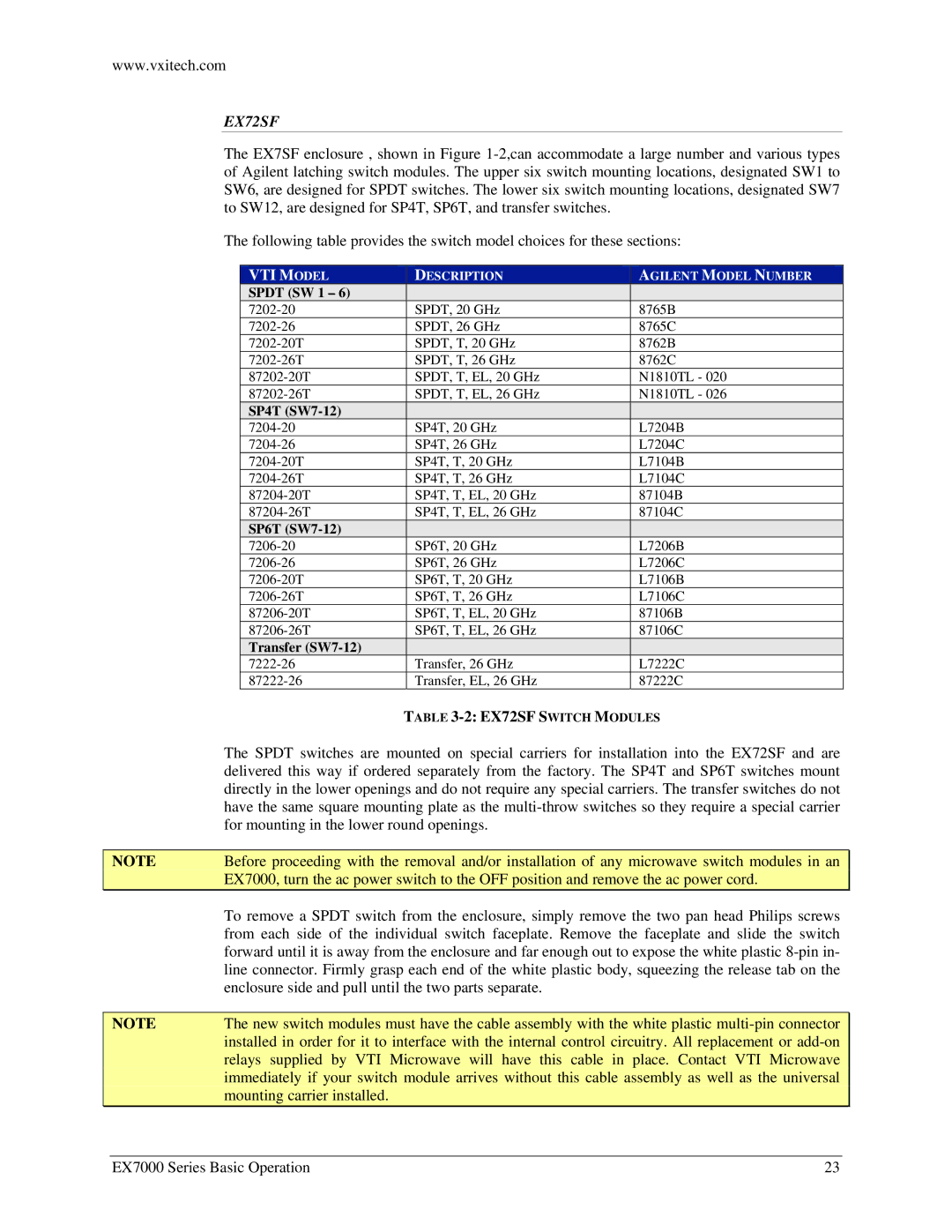
The following table provides the switch model choices for these sections:
VTI MODEL | DESCRIPTION | AGILENT MODEL NUMBER |
SPDT (SW 1 – 6) |
|
|
SPDT, 20 GHz | 8765B | |
SPDT, 26 GHz | 8765C | |
SPDT, T, 20 GHz | 8762B | |
SPDT, T, 26 GHz | 8762C | |
SPDT, T, EL, 20 GHz | N1810TL - 020 | |
SPDT, T, EL, 26 GHz | N1810TL - 026 | |
SP4T |
|
|
SP4T, 20 GHz | L7204B | |
SP4T, 26 GHz | L7204C | |
SP4T, T, 20 GHz | L7104B | |
SP4T, T, 26 GHz | L7104C | |
SP4T, T, EL, 20 GHz | 87104B | |
SP4T, T, EL, 26 GHz | 87104C | |
SP6T |
|
|
SP6T, 20 GHz | L7206B | |
SP6T, 26 GHz | L7206C | |
SP6T, T, 20 GHz | L7106B | |
SP6T, T, 26 GHz | L7106C | |
SP6T, T, EL, 20 GHz | 87106B | |
SP6T, T, EL, 26 GHz | 87106C | |
Transfer |
|
|
Transfer, 26 GHz | L7222C | |
Transfer, EL, 26 GHz | 87222C |
| TABLE |
| The SPDT switches are mounted on special carriers for installation into the EX72SF and are |
| delivered this way if ordered separately from the factory. The SP4T and SP6T switches mount |
| directly in the lower openings and do not require any special carriers. The transfer switches do not |
| have the same square mounting plate as the |
| for mounting in the lower round openings. |
|
|
NOTE | Before proceeding with the removal and/or installation of any microwave switch modules in an |
| EX7000, turn the ac power switch to the OFF position and remove the ac power cord. |
| To remove a SPDT switch from the enclosure, simply remove the two pan head Philips screws |
| from each side of the individual switch faceplate. Remove the faceplate and slide the switch |
| forward until it is away from the enclosure and far enough out to expose the white plastic |
| line connector. Firmly grasp each end of the white plastic body, squeezing the release tab on the |
| enclosure side and pull until the two parts separate. |
|
|
NOTE | The new switch modules must have the cable assembly with the white plastic |
| installed in order for it to interface with the internal control circuitry. All replacement or |
| relays supplied by VTI Microwave will have this cable in place. Contact VTI Microwave |
| immediately if your switch module arrives without this cable assembly as well as the universal |
| mounting carrier installed. |
EX7000 Series Basic Operation | 23 |