VXI Technology, Inc.
Trigger Bus Connectors
The EX7000 provides an LXI compatible trigger bus connector set on the rear panel of the instrument. Both connectors have the same pin assignments and are wired in parallel. For more information on the LXI Trigger Bus and creating an appropriate cable, please visit www.lxistandard.org and refer to LXI Standard Revision 1.2 and LXI Trigger Bus Cable and Terminator Specifications Rev 1.1. The trigger bus pin assignments are provided on the next page.
Trigger Bus Connectors
Pin | Signal | Pin | Signal |
1 | +3.3 V | 14 | RP_TRIG_P0 |
2 | GND | 15 | RP_TRIG_N0 |
3 | RP_TRIG_P1 | 16 | RESERVED |
4 | RP_TRIG_N1 | 17 | RP_TRIG_P2 |
5 | GND | 18 | RP_TRIG_N2 |
6 | RP_TRIG_P3 | 19 | GND |
7 | RP_TRIG_N3 | 20 | RP_TRIG_P4 |
8 | GND | 21 | RP_TRIG_N4 |
9 | RP_TRIG_P5 | 22 | GND |
10 | RP_TRIG_N5 | 23 | RP_TRIG_P6 |
11 | RESERVED | 24 | RP_TRIG_N6 |
12 | RP_TRIG_P7 | 25 | RESERVED |
13RP_TRIG_N7
1 | 13 |
14 | 25 |
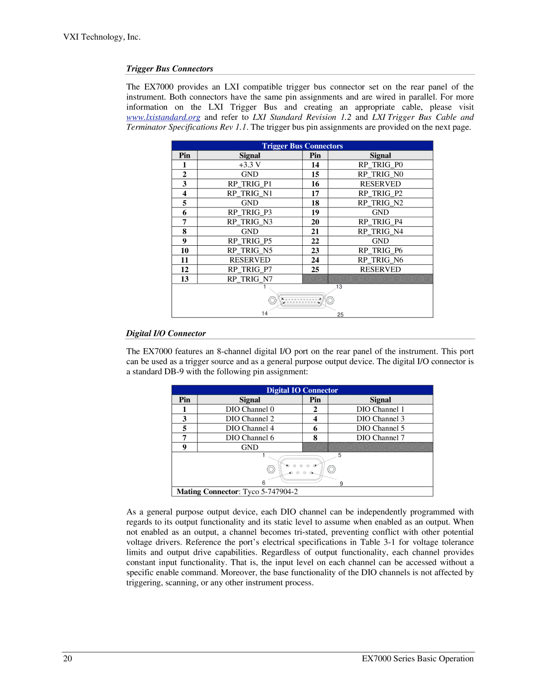
Digital I/O Connector
The EX7000 features an
Digital IO Connector
Pin | Signal | Pin | Signal |
1 | DIO Channel 0 | 2 | DIO Channel 1 |
3 | DIO Channel 2 | 4 | DIO Channel 3 |
5 | DIO Channel 4 | 6 | DIO Channel 5 |
7 | DIO Channel 6 | 8 | DIO Channel 7 |
9GND
1 | 5 |
6 | 9 |
Mating Connector: Tyco
As a general purpose output device, each DIO channel can be independently programmed with regards to its output functionality and its static level to assume when enabled as an output. When not enabled as an output, a channel becomes
20 | EX7000 Series Basic Operation |