VXI Technology, Inc.
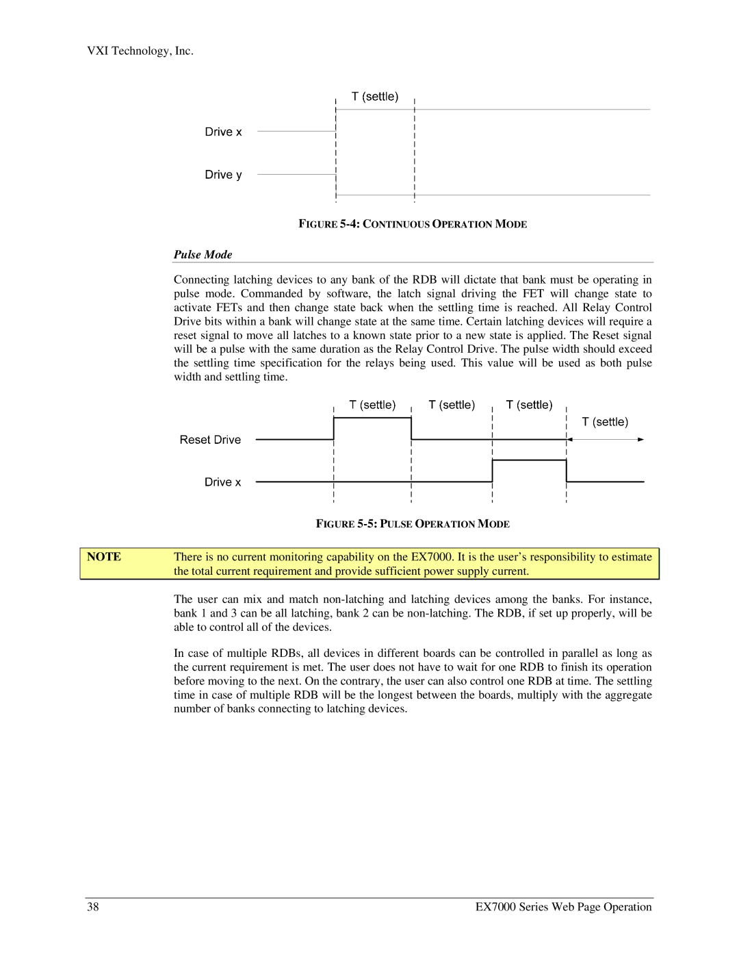
FIGURE 5-4: CONTINUOUS OPERATION MODE
Pulse Mode
Connecting latching devices to any bank of the RDB will dictate that bank must be operating in pulse mode. Commanded by software, the latch signal driving the FET will change state to activate FETs and then change state back when the settling time is reached. All Relay Control Drive bits within a bank will change state at the same time. Certain latching devices will require a reset signal to move all latches to a known state prior to a new state is applied. The Reset signal will be a pulse with the same duration as the Relay Control Drive. The pulse width should exceed the settling time specification for the relays being used. This value will be used as both pulse width and settling time.
| FIGURE |
|
|
NOTE | There is no current monitoring capability on the EX7000. It is the user’s responsibility to estimate |
| the total current requirement and provide sufficient power supply current. |
| The user can mix and match |
| bank 1 and 3 can be all latching, bank 2 can be |
| able to control all of the devices. |
| In case of multiple RDBs, all devices in different boards can be controlled in parallel as long as |
| the current requirement is met. The user does not have to wait for one RDB to finish its operation |
| before moving to the next. On the contrary, the user can also control one RDB at time. The settling |
| time in case of multiple RDB will be the longest between the boards, multiply with the aggregate |
| number of banks connecting to latching devices. |
38 | EX7000 Series Web Page Operation |
