INSTALLATION
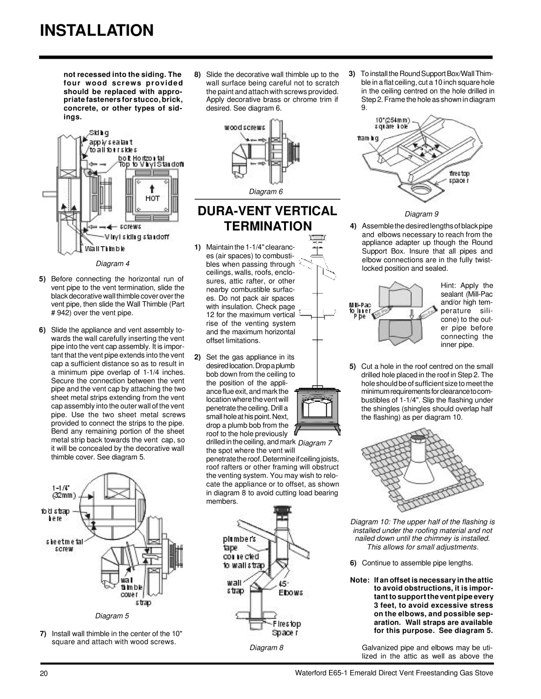
not recessed into the siding. The four wood screws provided should be replaced with appro- priate fasteners for stucco, brick, concrete, or other types of sid- ings.
8)Slide the decorative wall thimble up to the wall surface being careful not to scratch the paint and attach with screws provided. Apply decorative brass or chrome trim if desired. See diagram 6.
3)To install the Round Support Box/Wall Thim- ble in a flat ceiling, cut a 10 inch square hole in the ceiling centred on the hole drilled in Step 2. Frame the hole as shown in diagram 9.
Diagram 4
5)Before connecting the horizontal run of vent pipe to the vent termination, slide the black decorative wall thimble cover over the vent pipe, then slide the Wall Thimble (Part
# 942) over the vent pipe.
6)Slide the appliance and vent assembly to- wards the wall carefully inserting the vent pipe into the vent cap assembly. It is impor- tant that the vent pipe extends into the vent cap a sufficient distance so as to result in a minimum pipe overlap of
Diagram 5
7)Install wall thimble in the center of the 10" square and attach with wood screws.
Diagram 6
DURA-VENT VERTICAL
TERMINATION
1)Maintain the
12 for the maximum vertical rise of the venting system and the maximum horizontal offset limitations.
2)Set the gas appliance in its desired location. Drop a plumb bob down from the ceiling to the position of the appli- ance flue exit, and mark the location where the vent will penetrate the ceiling. Drill a small hole at his point. Next, drop a plumb bob from the roof to the hole previously
drilled in the ceiling, and mark Diagram 7 the spot where the vent will
penetrate the roof. Determine if ceiling joists, roof rafters or other framing will obstruct the venting system. You may wish to relo- cate the appliance or to offset, as shown in diagram 8 to avoid cutting load bearing members.
Diagram 8
Diagram 9
4)Assemble the desired lengths of black pipe and elbows necessary to reach from the appliance adapter up though the Round Support Box. Insure that all pipes and elbow connections are in the fully twist- locked position and sealed.
Hint: Apply the sealant
5)Cut a hole in the roof centred on the small drilled hole placed in the roof in Step 2. The hole should be of sufficient size to meet the minimum requirements for clearance to com- bustibles of
Diagram 10: The upper half of the flashing is installed under the roofing material and not nailed down until the chimney is installed.
This allows for small adjustments.
6)Continue to assemble pipe lengths.
Note: If an offset is necessary in the attic to avoid obstructions, it is impor- tant to support the vent pipe every 3 feet, to avoid excessive stress on the elbows, and possible sep- aration. Wall straps are available for this purpose. See diagram 5.
Galvanized pipe and elbows may be uti- lized in the attic as well as above the
20
Waterford