INSTALLATION
Converting a Masonry Chimney
Important: The existing masonry flue opening needs to have an area of at least a 36 sq. in. to insure proper intake/ex- haust flow.
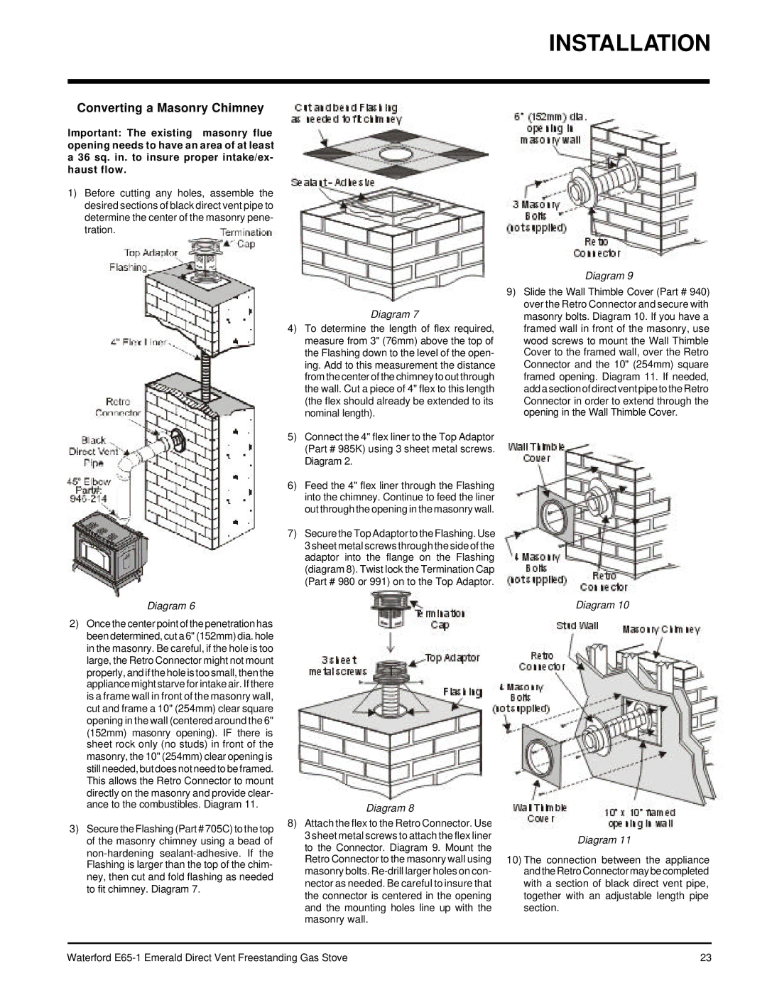
1)Before cutting any holes, assemble the desired sections of black direct vent pipe to determine the center of the masonry pene- tration.
Diagram 6
2)Once the center point of the penetration has been determined, cut a 6" (152mm) dia. hole in the masonry. Be careful, if the hole is too large, the Retro Connector might not mount properly, and if the hole is too small, then the appliance might starve for intake air. If there is a frame wall in front of the masonry wall, cut and frame a 10" (254mm) clear square opening in the wall (centered around the 6" (152mm) masonry opening). IF there is sheet rock only (no studs) in front of the masonry, the 10" (254mm) clear opening is still needed, but does not need to be framed. This allows the Retro Connector to mount directly on the masonry and provide clear- ance to the combustibles. Diagram 11.
3)Secure the Flashing (Part # 705C) to the top of the masonry chimney using a bead of
Diagram 7
4)To determine the length of flex required, measure from 3" (76mm) above the top of the Flashing down to the level of the open- ing. Add to this measurement the distance from the center of the chimney to out through the wall. Cut a piece of 4" flex to this length (the flex should already be extended to its nominal length).
5)Connect the 4" flex liner to the Top Adaptor (Part # 985K) using 3 sheet metal screws. Diagram 2.
6)Feed the 4" flex liner through the Flashing into the chimney. Continue to feed the liner out through the opening in the masonry wall.
7)Secure the Top Adaptor to the Flashing. Use 3 sheet metal screws through the side of the adaptor into the flange on the Flashing (diagram 8). Twist lock the Termination Cap (Part # 980 or 991) on to the Top Adaptor.
Diagram 8
8)Attach the flex to the Retro Connector. Use 3 sheet metal screws to attach the flex liner to the Connector. Diagram 9. Mount the Retro Connector to the masonry wall using masonry bolts.
Diagram 9
9)Slide the Wall Thimble Cover (Part # 940) over the Retro Connector and secure with masonry bolts. Diagram 10. If you have a framed wall in front of the masonry, use wood screws to mount the Wall Thimble Cover to the framed wall, over the Retro Connector and the 10" (254mm) square framed opening. Diagram 11. If needed, add a section of direct vent pipe to the Retro Connector in order to extend through the opening in the Wall Thimble Cover.
Diagram 10
Diagram 11
10)The connection between the appliance and the Retro Connector may be completed with a section of black direct vent pipe, together with an adjustable length pipe section.
Waterford | 23 |