INSTALLATION
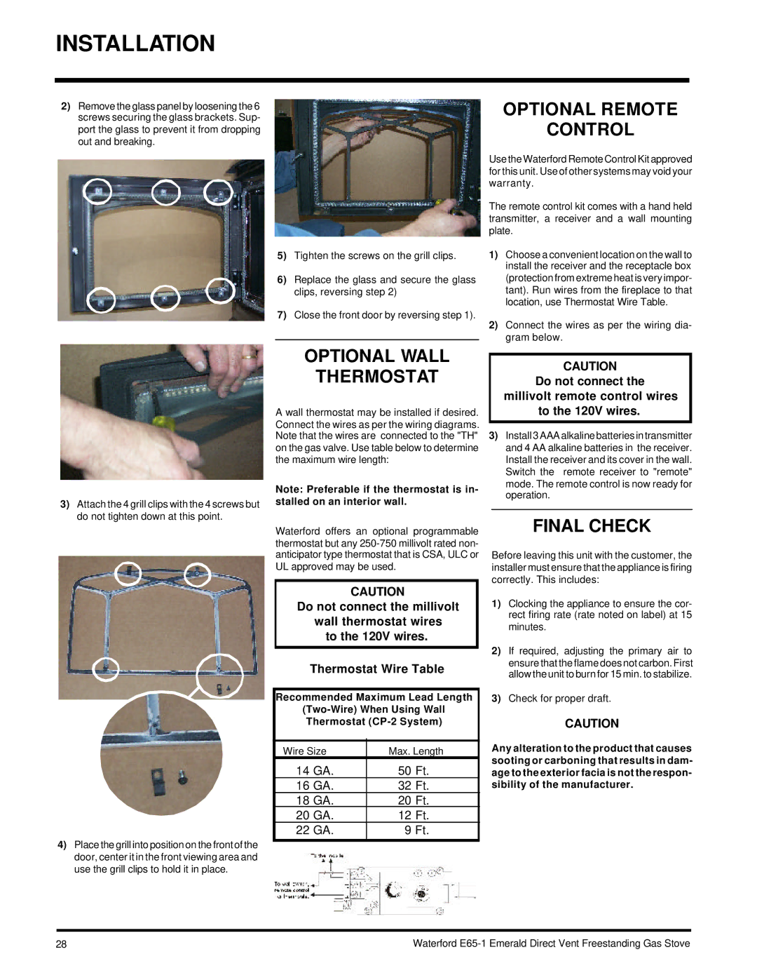
2)Remove the glass panel by loosening the 6 screws securing the glass brackets. Sup- port the glass to prevent it from dropping out and breaking.
OPTIONAL REMOTE
CONTROL
5)Tighten the screws on the grill clips.
6)Replace the glass and secure the glass clips, reversing step 2)
7)Close the front door by reversing step 1).
Use the Waterford Remote Control Kit approved for this unit. Use of other systems may void your warranty.
The remote control kit comes with a hand held transmitter, a receiver and a wall mounting plate.
1)Choose a convenient location on the wall to install the receiver and the receptacle box (protection from extreme heat is very impor- tant). Run wires from the fireplace to that location, use Thermostat Wire Table.
2)Connect the wires as per the wiring dia- gram below.
3)Attach the 4 grill clips with the 4 screws but do not tighten down at this point.
4)Place the grill into position on the front of the door, center it in the front viewing area and use the grill clips to hold it in place.
OPTIONAL WALL
THERMOSTAT
A wall thermostat may be installed if desired. Connect the wires as per the wiring diagrams. Note that the wires are connected to the "TH" on the gas valve. Use table below to determine the maximum wire length:
Note: Preferable if the thermostat is in- stalled on an interior wall.
Waterford offers an optional programmable thermostat but any
CAUTION
Do not connect the millivolt
wall thermostat wires to the 120V wires.
Thermostat Wire Table
Recommended Maximum Lead Length
Thermostat
Wire Size | Max. Length |
| |
14 GA. | 50 | Ft. |
|
16 GA. | 32 | Ft. |
|
18 GA. | 20 | Ft. |
|
20 GA. | 12 | Ft. |
|
22 GA. | 9 | Ft. |
|
|
|
|
|
CAUTION
Do not connect the
millivolt remote control wires to the 120V wires.
3)Install 3 AAA alkaline batteries in transmitter and 4 AA alkaline batteries in the receiver. Install the receiver and its cover in the wall. Switch the remote receiver to "remote" mode. The remote control is now ready for operation.
FINAL CHECK
Before leaving this unit with the customer, the installer must ensure that the appliance is firing correctly. This includes:
1)Clocking the appliance to ensure the cor- rect firing rate (rate noted on label) at 15 minutes.
2)If required, adjusting the primary air to ensure that the flame does not carbon. First allow the unit to burn for 15 min. to stabilize.
3)Check for proper draft.
CAUTION
Any alteration to the product that causes sooting or carboning that results in dam- age to the exterior facia is not the respon- sibility of the manufacturer.
28 | Waterford |