INSTALLATION
DV STOVE HORIZONTAL VENT KIT (#
Review the following sequence of instructions which are typical of most installations. The sequence may vary depending on wall thick-
ness. Refer to pages 10 to 14 for vent location and clearance dimensions. If a Vent Restrictor is required it must be installed BEFORE any venting is attached to the stove.
1)Set the unit in its desired location. Check to determine if wall studs will be in the way of the venting system, adjust location until all clearances are met and there are no ob- structions.
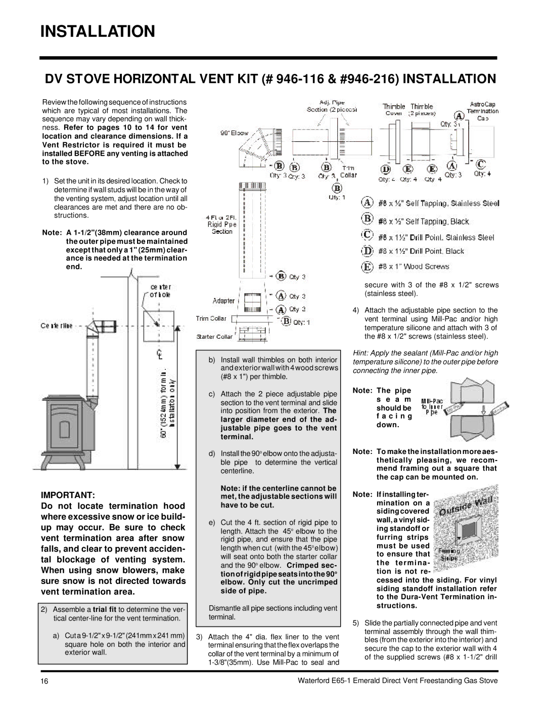
Note: A
IMPORTANT:
Do not locate termination hood where excessive snow or ice build- up may occur. Be sure to check vent termination area after snow falls, and clear to prevent acciden- tal blockage of venting system. When using snow blowers, make sure snow is not directed towards vent termination area.
2)Assemble a trial fit to determine the ver- tical
a)Cut a
b)Install wall thimbles on both interior and exterior wall with 4 wood screws (#8 x 1") per thimble.
c)Attach the 2 piece adjustable pipe section to the vent terminal and slide into position from the exterior. The larger diameter end of the ad- justable pipe goes to the vent terminal.
d)Install the 90o elbow onto the adjusta- ble pipe to determine the vertical centerline.
Note: if the centerline cannot be met, the adjustable sections will have to be cut.
e)Cut the 4 ft. section of rigid pipe to length. Attach the 45o elbow to the rigid pipe, and ensure that the pipe length when cut (with the 45oelbow) will seat onto both the starter collar and the 90o elbow. Crimped sec- tion of rigid pipe seats into the 90o elbow. Only cut the uncrimped side of pipe.
Dismantle all pipe sections including vent terminal.
3)Attach the 4" dia. flex liner to the vent terminal ensuring that the flex overlaps the collar of the vent terminal by a minimum of
secure with 3 of the #8 x 1/2" screws (stainless steel).
4)Attach the adjustable pipe section to the vent terminal using
Hint: Apply the sealant
Note: The pipe s e a m should be f a c i n g down.
Note: To make the installation more aes- thetically pleasing, we recom- mend framing out a square that the cap can be mounted on.
Note: If installing ter- mination on a sidingcovered wall, a vinyl sid- ing standoff or furring strips must be used to ensure that the termina - tion is not re-
cessed into the siding. For vinyl siding standoff installation refer to the
5)Slide the partially connected pipe and vent terminal assembly through the wall thim- bles (from the exterior into the interior) and secure the cap to the exterior wall with 4 of the supplied screws (#8 x
16 | Waterford |