INSTALLATION
point, stainless steel). Note: pilot holes will need to be drilled through the wall thimble on all 4 corners.
Note: The four screws provided for the vent cap should be replaced with appropriate fasteners for stucco, brick, concrete, or other types of sidings.
6)A bead of
7)Stretch the 4" dia. flex liner out fully and get a trial fit of the liner onto the 4" dia. starter collar.
8)Cut the 4" dia. flex liner to the desired size.
Hint: leave an extra 12" to 16" of length, this will make the final assembly easier to work with.
9)Secure the 4" dia. flex liner to the 4" adapter with
10)Slide the decorative Thimble Cover over the pipe sections and secure with 4 screws (#8 x
11)Slide the 90o elbow (crimp end up), the 45o elbow and the 4 ft. pipe section (crimp end up) over the 4" dia. flex liner.
12)Install the spring spacers onto the pipe sections.
13)Secure the 4" dia. flex liner with adapter onto the stove collar. Put a bead of
14)Attach the 45o elbow onto the starter collar by sealing with
15)Attach the pipe section to the 45o elbow by sealing with
16)Attach the 90o elbow onto the pipe section by sealing with
17)Slide the adjustable pipe section onto the 90o elbow. Slide the trim collar over the adjustable pipe sections to cover the joint of the telescopic section.) The flex may have to be compressed back in order for the adjustable pipe to properly mate to the elbow. Seal with
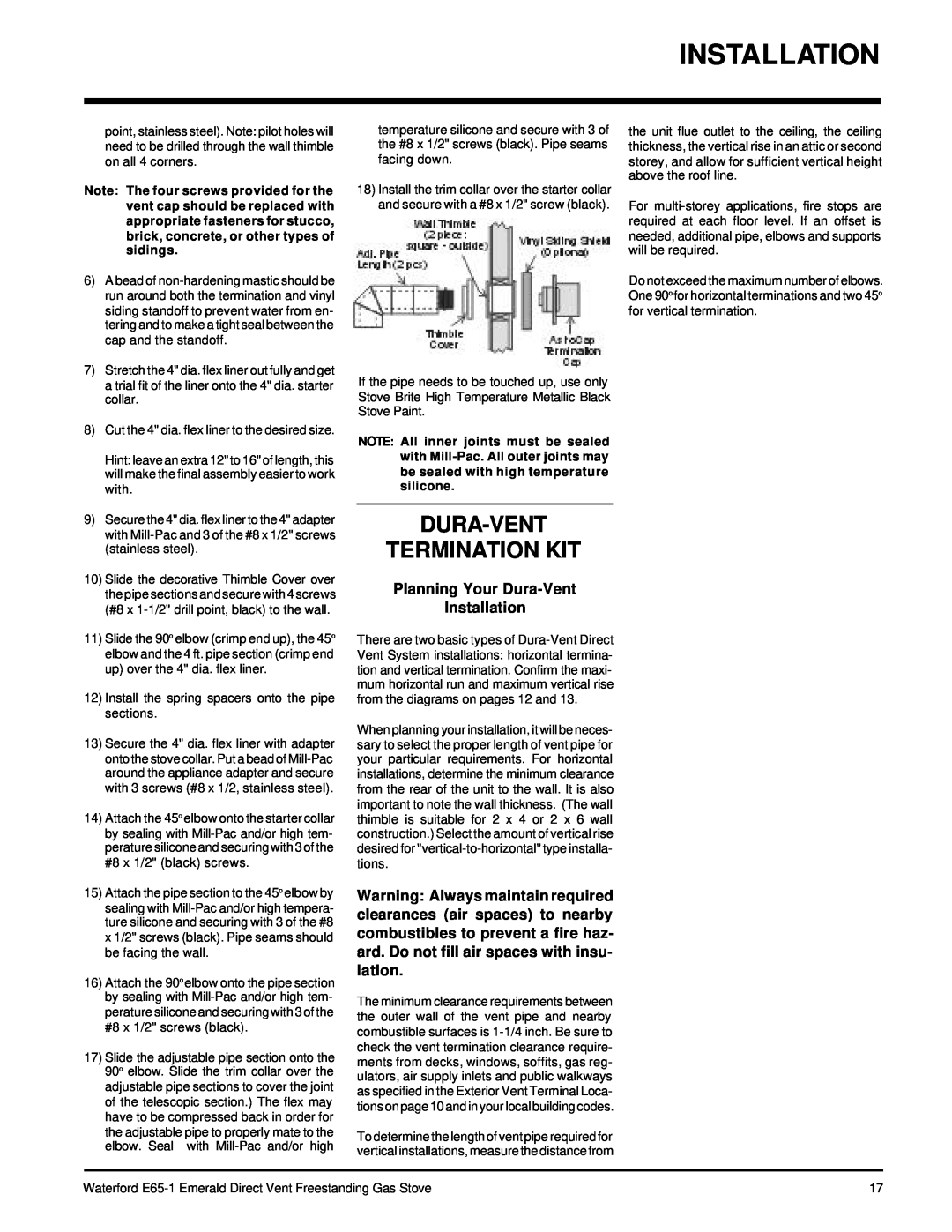
temperature silicone and secure with 3 of the #8 x 1/2" screws (black). Pipe seams facing down.
18)Install the trim collar over the starter collar and secure with a #8 x 1/2" screw (black).
If the pipe needs to be touched up, use only Stove Brite High Temperature Metallic Black Stove Paint.
NOTE: All inner joints must be sealed with
DURA-VENT
TERMINATION KIT
Planning Your Dura-Vent
Installation
There are two basic types of
When planning your installation, it will be neces- sary to select the proper length of vent pipe for your particular requirements. For horizontal installations, determine the minimum clearance from the rear of the unit to the wall. It is also important to note the wall thickness. (The wall thimble is suitable for 2 x 4 or 2 x 6 wall construction.) Select the amount of vertical rise desired for
Warning: Always maintain required clearances (air spaces) to nearby combustibles to prevent a fire haz- ard. Do not fill air spaces with insu- lation.
The minimum clearance requirements between the outer wall of the vent pipe and nearby combustible surfaces is
To determine the length of vent pipe required for vertical installations, measure the distance from
the unit flue outlet to the ceiling, the ceiling thickness, the vertical rise in an attic or second storey, and allow for sufficient vertical height above the roof line.
For
Do not exceed the maximum number of elbows. One 90o for horizontal terminations and two 45o for vertical termination.
Waterford | 17 |