INSTALLATION
DURA-VENT HORIZONTAL INSTALLATIONS
1)Set the unit in its desired location. Check to determine if wall studs or roof rafters are in the way when the venting system is attached. If this is the case, you may want to adjust the location of the unit.
2)Direct Vent pipe and fittings are designed with special
tion of pipe and elbows to the appliance adapter with pipe seams oriented towards the wall or ceiling, as much out of view as pos- sible. The final position- ing of the pipe and 90o elbow assembly is de- termined by the mount- ing orienta-
tion of the adapter on the stove and twist - locked for a solid con- nection.
Note:
a)
Diagram 1:
Hint: Apply silicone to female end.
b)Horizontal runs of vent must be sup- ported every three feet. Wall straps are available for this purpose.
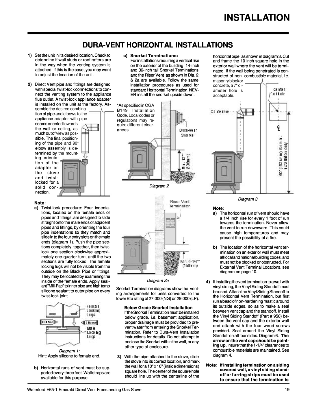
c)Snorkel Terminations:
For installations requiring a vertical rise on the exterior of the building,
*As specified in CGA B149 Installation Code. Local codes or regulations may re- quire different clear- ances.
Diagram 2
Diagram 2a
Snorkel Termination diagrams show the vent- ing arrangements for units converted to the lower Btu rating of 27,000 (NG) or 29,000 (LP).
Below Grade Snorkel Installation
If the Snorkel Termination must be installed below grade, i.e. basement application, proper drainage must be provided to pre- vent water from entering the Snorkel Ter- mination. Refer to
3)With the pipe attached to the stove, slide the stove into its correct location, and mark the wall for a 10" x 10" (inside dimensions) square hole. The center of the square hole should line up with the centerline of the
horizontal pipe, as shown in diagram 3. Cut and frame the 10 inch square hole in the exterior wall where the vent will be termi- nated. If the wall being penetrated is con- structed of non- combustible material, i.e. masonryblockor
concrete, a 7" di- ameter hole is acceptable.
Diagram 3
Note:
a)The horizontal run of vent should have a 1/4 inch rise for every 1 foot of run towards the termination. Never allow the vent to run downward. This could cause high temperatures and may present the possibility of a fire.
b)The location of the horizontal vent ter- mination on an exterior wall must meet all local and national building codes, and must not be blocked or obstructed. For External Vent Terminal Locations, see diagram on page 10.
4)If installing the vent termination to a wall with vinyl siding, the Vinyl Siding Standoff must be used. Attach the Vinyl Siding Standoff to the Horizontal Vent Termination, but first run a bead of
Note: If installing termination on a siding covered wall, a vinyl siding stand- off or furring strips must be used to ensure that the termination is
Waterford | 19 |