INSTALLATION
pages 11 and 12 for the required vent arrangements. If installed into a manufac- tured home the unit must be bolted down to the floor.
4)This appliance is Listed for bedroom instal- lations when used with a Listed Millivolt Thermostat. Some areas may have further requirements, check local codes before installation.
5)This appliance is Listed for Alcove installa- tions, maintain minimum Alcove clearances
as follows, minimum width of 41", a maximum depth of 24", and minimum ceiling height of 47".
6)We recommend that you plan your installa- tion on paper using exact measurements for clearances and floor protection before actually installing this appliance. Have a qualified building inspector review your plans before installation.
GENERAL SAFETY INFORMATION
1)The appliance installation must conform with local Canadian Electrical Code.
2)The appliance when installed, must be elec- trically grounded in accordance with local codes, or in the absence of local codes with the current National Electrical Code, ANSI/ NFPA 70 or CSA C22.1 Canadian Electrical Code.
3)The appliance should be inspected for shipping damage before use andserviced annuallybyaprofessionalserviceper- son. More frequent cleaning may be re- quired due to excessive lint from carpeting, bedding material, etc. It is imperative that control compartments, and circulating air passageways of the appliance be kept clean and free from excessive lint from carpeting.
4)See general construction and assembly instructions. The appliance and vent should be enclosed when installed in or passing through a living area, where children may come in contact with it.
5)This appliance must be connected to the
specified vent and termination cap to the
outside of the building envelope. Nev - er vent to another room or inside a building. Make sure that the vent is fitted as per the instructions starting on page 9.
6)Inspect the venting system annually for blockage and any signs of deterioration.
7)Venting terminals shall not be recessed into a wall or siding.
8)Any safety glass removed for servicing must be replaced prior to operating the appliance.
9)To prevent injury, do not allow anyone who is unfamiliar with the operation to use the fireplace.
Emissions from burning wood or gas could contain chemicals known to the State of California to cause cancer, birth defects or other reproductive harm.
INSTALLATION
CHECKLIST
1)Check Clearances to Combustibles (page 7), location of unit (page 8) and venting requirements (pages 9 to 18).
2)Install vent restrictors, page 9.
3)Install Optional Fan, see page 8.
4)Install venting: Check all venting require- ments, pages 9 to 18. Vertical Termination with
5)Make gas connections, page 24. Test the pilot. Must be as per diagram, page 31.
If converting to Propane or reducing Btu input, make changes prior see pages 25 & 26.
6)Test Gas Pressure, page 25.
7)Install logs and embers where indicated on page 27.
8)Install optional Remote Control, or Wall Ther- mostat, page 28.
9)Final check, page 28.
Before leaving this unit with the customer, the installer must ensure that the appliance is firing correctly and operation fully explained to customer.
This includes:
1)Clocking the appliance to ensure the cor- rect firing rate (rate noted on label) after burning appliance for 15 minutes.
2)If required, adjusting the primary air to ensure that the flame does not carbon. First allow the unit to burn for
CAUTION: Any alteration to the product that causes sooting or carboning that results in damage is not the responsibil- ity of the manufacturer.
CLEARANCES TO COMBUSTIBLES
The clearances listed are MINIMUM distances. Measure the clearance to both the appliance and the chimney connector. The farthest
distance is correct if the two clearances do not coincide.
For example, if the appliance is set as indicated in one of the figures but the connector is too close, move the stove until the correct clear- ance to the connector is obtained.
This appliance may be installed only with the clearances as shown in the situations pictured.
Do not combine clearances from one type of installation with another in order to achieve closer clearances.
This unit can be installed on a solid combustible surface like a wood floor. This unit can also be installed directly on carpeting or vinyl.
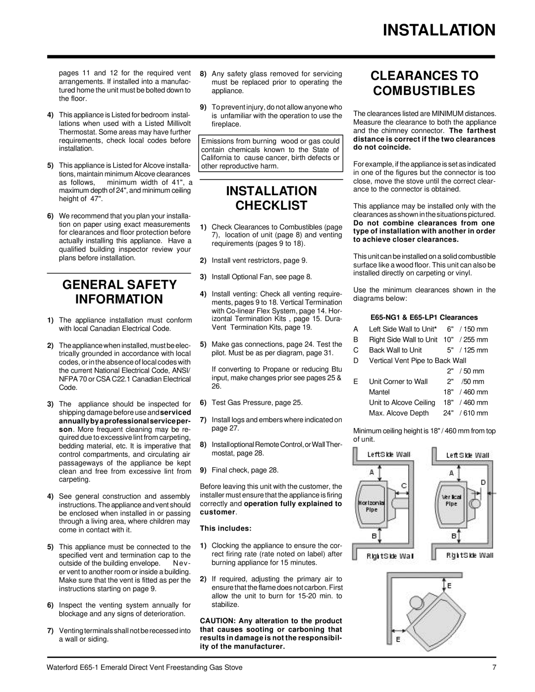
Use the minimum clearances shown in the diagrams below:
E65-NG1 & E65-LP1 Clearances
A Left Side Wall to Unit* | 6" | / 150 mm |
B Right Side Wall to Unit | 10" | / 255 mm |
C Back Wall to Unit | 5" | / 125 mm |
D Vertical Vent Pipe to Back Wall | ||
| 2" | / 50 mm |
E Unit Corner to Wall | 2" | /50 mm |
Mantel | 18" | / 460 mm |
Unit to Alcove Ceiling | 18" | / 460 mm |
Max. Alcove Depth | 24" | / 610 mm |
Minimum ceiling height is 18" / 460 mm from top of unit.
Waterford | 7 |