4

Instalación de los soportes


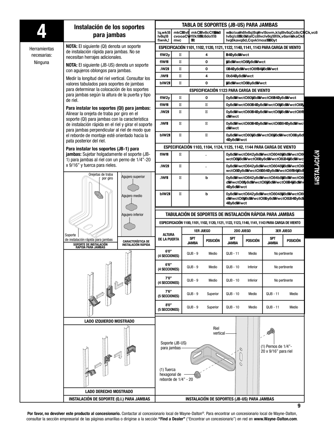
TABLA DE SOPORTES (JB-US) PARA JAMBAS


para jambas

ALTURA

NRO. DE

NRO. DE SOPORTES­

UBICACIÓN DE LA LÍNEA CENTRAL DE LOS SOPORTES


DE LA

SECCIO-

PARA JAMBAS (CADA

DE LAS JAMBAS MEDIDOS DESDE LA PARTE INFERIOR


PUERTA

NES

JAMBA)


DEL RIEL (TOLERANCIA: ± 2”)


Herramientas

NOTA: El siguiente (QI) denota un soporte

ESPECIFICACIÓN 1101, 1102, 1120, 1121, 1122, 1140, 1141, 1143 PARA CARGA DE VIENTO


de instalación rápida para jambas. No se


necesarias:

6’-0”

4


1

33 1/2” (JB-US)


necesitan herrajes adicionales.


Ninguna

6’-6’’

4


2

34” (JB-US), 56” (JB-US)


NOTA: El siguiente (JB-US) denota un soporte


7’-0’’

4


2

29 1/2” (JB-US), 63 1/4” (JB-US)


con agujeros oblongos para jambas.


Medir la longitud del riel vertical. Consultar los

7’-6’’

5


1

28 1/2” (JB-US)


8’-0’’

5


2

34” (JB-US), 58” (JB-US)


valores tabulados para soportes de jambas


para determinar la colocación de los soportes


ESPECIFICACIÓN 1123 PARA CARGA DE VIENTO


para jambas según la altura de la puerta y tipo

6’-0”

4


2

2” (JB-US), 23” (JB-US), 33 1/2” (JB-US)


de riel.


6’-6’’

4


3

2” (JB-US), 23 1/2” (JB-US), 34” (JB-US), 56” (JB-US)


Para instalar los soportes (QI) para jambas:


7’-0’’

4


4

2” (JB-US), 25 1/2” (JB-US), 34” (JB-US), 63 1/4”


Alinear la orejeta de traba por giro en el


(JB-US)


soporte (QI) para jambas con la característica


7’-6’’

5


4

2” (JB-US), 24 1/2” (JB-US), 32 1/2” (JB-US), 49”


de instalación rápida en el riel y girar el soporte


para jambas perpendicular al riel de modo que


(JB-US)


el reborde de montaje esté orientado hacia la

8’-0’’

5


5

2” (JB-US), 23” (JB-US), 34” (JB-US), 58” (JB-US), 75


pata posterior del riel.


1/2” (JB-US)


Para instalar los soportes (JB-1) para

ESPECIFICACIÓN 1103, 1104, 1124, 1125, 1142, 1144 PARA CARGA DE VIENTO

INSTALACIÓN


jambas: Sujetar holgadamente el soporte (JB-

6’-6’’

4


7

2” (JB-US), 10” (JB-US), 21 3/4” (JB-US), 29 3/4” (JB-


1) para jambas al riel con un perno de 1/4”-20


US), 39” (JB-US), 48” (JB-US), 57 1/4” (JB-US)


x 9/16” y tuerca para rieles.


7’-0’’

4


7

2” (JB-US), 10” (JB-US), 21 3/4” (JB-US), 29 3/4” (JB-


Orejetas de traba


US), 42” (JB-US), 52 1/2” (JB-US), 63 1/4” (JB-US)


Agujero superior

7’-6’’

5


8

2” (JB-US), 10” (JB-US), 18 3/4” (JB-US), 26 3/4”


por giro


(JB-US), 36” (JB-US), 45” (JB-US), 54 1/4” (JB-US), 74


1/2” (JB-US)


Agujero medio

8’-0’’

5


8

2” (JB-US), 10” (JB-US), 21 3/4” (JB-US), 29 3/4”


(JB-US), 39” (JB-US), 48” (JB-US), 57 1/2” (JB-US), 75


1/2” (JB-US)


Agujero inferior

TABULACIÓN DE SOPORTES DE INSTALACIÓN RÁPIDA PARA JAMBAS


ESPECIFICACIÓN 1100, 1101, 1102, 1120, 1121, 1122, 1123, 1140, 1141, 1143 PARA CARGA DE VIENTO


Soporte


ALTURA

1ER JUEGO

2DO JUEGO

3ER JUEGO


SPT


SPT


SPT


de instalación rápida para jambas

CARACTERÍSTICA DE

DE LA PUERTA

POSICIÓN

POSICIÓN

POSICIÓN


SOPORTE DE INSTALACIÓN


JAMBA

JAMBA

JAMBA


INSTALACIÓN RÁPIDA


RÁPIDA PARA JAMBAS


6’0”


QIJB - 9

Medio

QIJB - 11


Medio

No pertinente


(4 SECCIONES)


6’6”


QIJB - 9

Medio

QIJB - 10


Inferior

No pertinente


(4 SECCIONES)


7’0”


QIJB - 9

Medio

QIJB - 10


Inferior

No pertinente


(4 SECCIONES)


7’6”


QIJB - 9

Superior

QIJB - 10


Medio

QIJB - 11

Medio


(5 SECCIONES)


8’0”


QIJB - 9

Superior

QIJB - 10


Medio

QIJB - 11

Medio


(5 SECCIONES)


LADO IZQUIERDO MOSTRADO


Riel


vertical


Soporte (JB-US)


(1) Pernos de 1/4”-


para jambas


20 x 9/16” para riel


(1) Tuerca


hexagonal de


reborde de 1/4” - 20


LADO DERECHO MOSTRADO


INSTALACIÓN DE SOPORTE (Q.I.) PARA JAMBAS


INSTALACIÓN DE SOPORTES (JB-US) PARA JAMBAS


9

Por favor, no devolver este producto al concesionario. Contactar al concesionario local de Wayne-Dalton®. Para encontrar un concesionario local de Wayne-Dalton, consultar la sección empresarial de las páginas amarillas o dirigirse a la sección “Find a Dealer” (“Encontrar un concesionario”) en red en www.Wayne-Dalton.com.

Page 9
Image 9
Wayne-Dalton 8000 Necesitan herrajes adicionales, Con agujeros oblongos para jambas, De riel, Pata posterior del riel

8000, 8100, 8200 specifications

Wayne-Dalton, a renowned name in the garage door industry, offers a variety of products that combine durability, style, and innovative technology. Among their popular models are the Wayne-Dalton 8100, 8124, and 8024 garage doors, each with distinct features and characteristics that cater to different customer needs.

The Wayne-Dalton 8100 garage door is a steel door designed for maximum durability and energy efficiency. Constructed from a robust, 24-gauge steel, this model features a polyester primer finish, protecting it from rust and corrosion. The door's insulated design minimizes energy loss, offering an R-value of up to 10. This model is an excellent choice for homeowners seeking a balance between functionality and aesthetic appeal. The Wayne-Dalton 8100 is also customizable, available in various colors and panel designs, allowing homeowners to match their door with their home’s exterior.

Next, the Wayne-Dalton 8124 is designed with both security and insulation in mind. This model comprises steel sections with a polystyrene core, providing enhanced thermal efficiency and strength. With an impressive R-value of 13, the door effectively reduces heat transfer, making it ideal for climates with extreme temperatures. The 8124 is also equipped with a galvanized steel exterior, ensuring long-lasting durability. Additionally, it features a unique, patented TorqueMaster® lift system that allows for smooth, reliable operation while reducing the risk of injury and wear.

The Wayne-Dalton 8024 offers a blend of elegance and efficiency, with its sleek design and smooth surface. Constructed with high-quality insulation and featuring a classic raised panel design, the 8024 is perfect for homeowners who prioritize aesthetics without compromising functionality. The steel construction ensures longevity and resistance to dents and weather damage. The R-value of this model is also impressive, offering excellent insulation properties.

All three models, the 8100, 8124, and 8024, come with various design options and color choices, making them versatile for different architectural styles. Additionally, they each utilize Wayne-Dalton's advanced safety features, ensuring that users can operate them with peace of mind. With high-quality manufacturing and innovative technologies, Wayne-Dalton's garage doors remain a top choice for homeowners looking for reliable and stylish solutions for their homes.