WireSpeed ADSL Modem
User Guide
LED Indicators
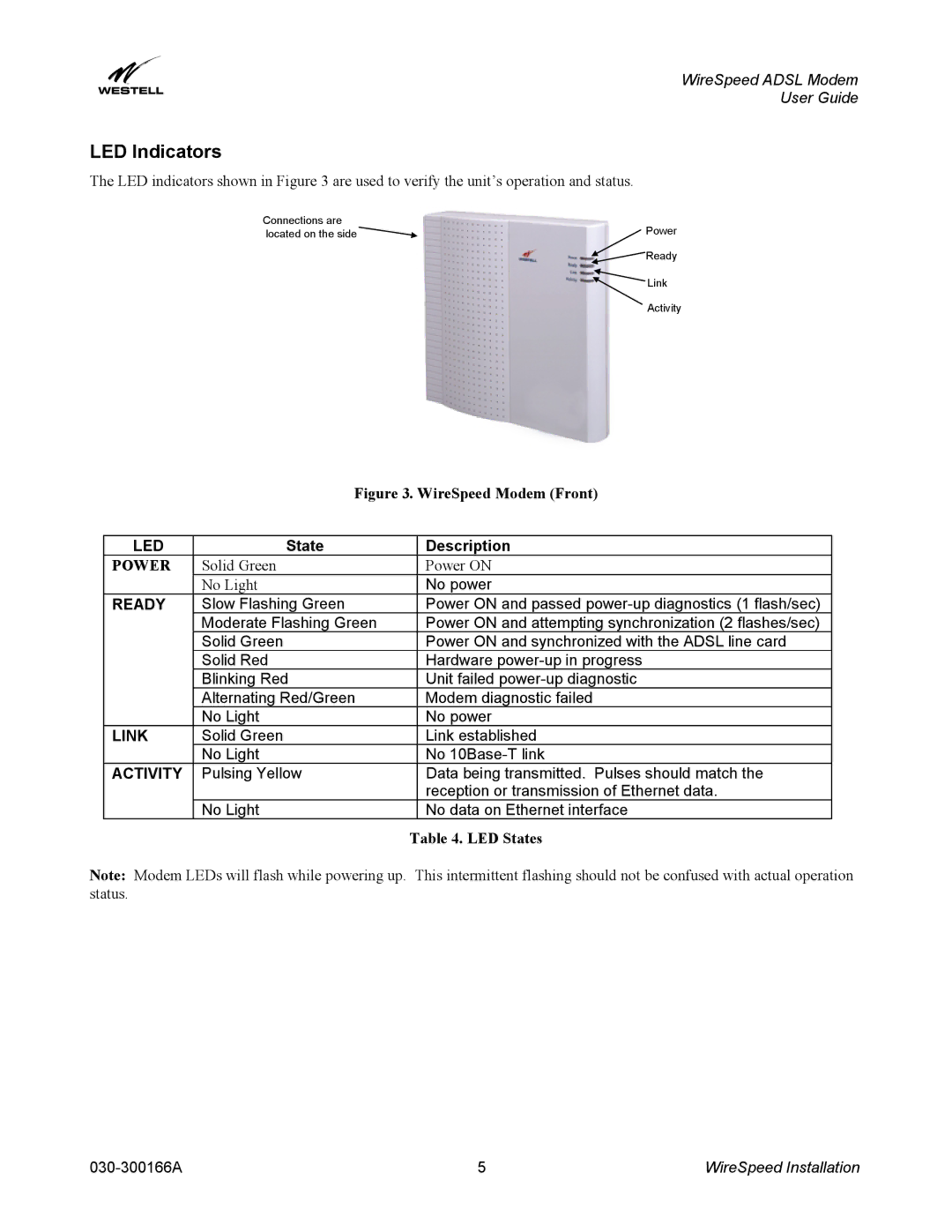
The LED indicators shown in Figure 3 are used to verify the unit’s operation and status.
Connections are | Power |
located on the side | |
| Ready |
| Link |
| Activity |
Figure 3. WireSpeed Modem (Front)
LED | State |
| Description |
POWER | Solid Green |
| Power ON |
| No Light |
| No power |
READY | Slow Flashing Green |
| Power ON and passed |
| Moderate Flashing Green |
| Power ON and attempting synchronization (2 flashes/sec) |
| Solid Green |
| Power ON and synchronized with the ADSL line card |
| Solid Red |
| Hardware |
| Blinking Red |
| Unit failed |
| Alternating Red/Green |
| Modem diagnostic failed |
| No Light |
| No power |
LINK | Solid Green |
| Link established |
| No Light |
| No |
ACTIVITY | Pulsing Yellow |
| Data being transmitted. Pulses should match the |
|
|
| reception or transmission of Ethernet data. |
| No Light |
| No data on Ethernet interface |
|
| Table 4. LED States | |
Note: Modem LEDs will flash while powering up. This intermittent flashing should not be confused with actual operation status.
5 | WireSpeed Installation |