Features and Specifications
Specifications
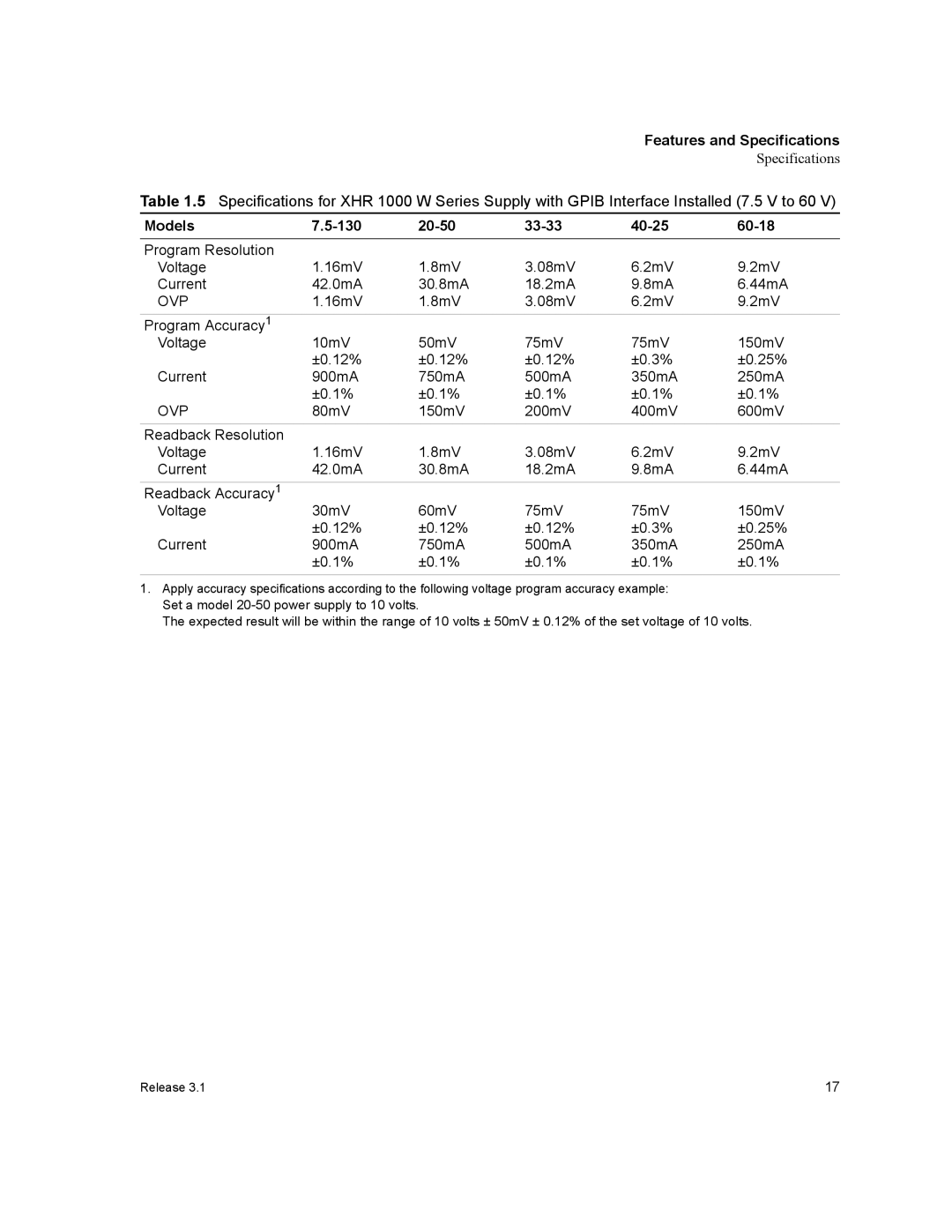
Table 1.5 Specifications for XHR 1000 W Series Supply with GPIB Interface Installed (7.5 V to 60 V)
Models |
|
|
|
|
|
Program Resolution | 1.16mV | 1.8mV | 3.08mV | 6.2mV | 9.2mV |
Voltage | |||||
Current | 42.0mA | 30.8mA | 18.2mA | 9.8mA | 6.44mA |
OVP | 1.16mV | 1.8mV | 3.08mV | 6.2mV | 9.2mV |
Program Accuracy1 |
|
|
|
|
|
Voltage | 10mV | 50mV | 75mV | 75mV | 150mV |
| ±0.12% | ±0.12% | ±0.12% | ±0.3% | ±0.25% |
Current | 900mA | 750mA | 500mA | 350mA | 250mA |
| ±0.1% | ±0.1% | ±0.1% | ±0.1% | ±0.1% |
OVP | 80mV | 150mV | 200mV | 400mV | 600mV |
Readback Resolution |
|
|
|
|
|
Voltage | 1.16mV | 1.8mV | 3.08mV | 6.2mV | 9.2mV |
Current | 42.0mA | 30.8mA | 18.2mA | 9.8mA | 6.44mA |
Readback Accuracy1 |
|
|
|
|
|
Voltage | 30mV | 60mV | 75mV | 75mV | 150mV |
| ±0.12% | ±0.12% | ±0.12% | ±0.3% | ±0.25% |
Current | 900mA | 750mA | 500mA | 350mA | 250mA |
| ±0.1% | ±0.1% | ±0.1% | ±0.1% | ±0.1% |
1.Apply accuracy specifications according to the following voltage program accuracy example: Set a model
The expected result will be within the range of 10 volts ± 50mV ± 0.12% of the set voltage of 10 volts.
Release 3.1 | 17 |