Installation and Configuration
Initial Inspection
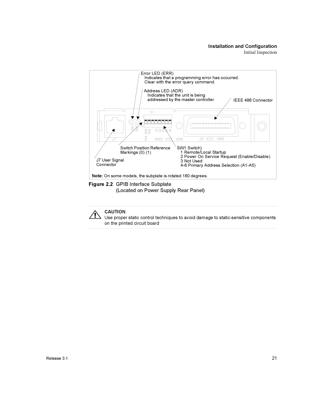
Error LED (ERR)
Indicates that a programming error has occurred.
Clear with the error query command.
Address LED (ADR) |
|
Indicates that the unit is being |
|
addressed by the master controller. | IEEE 488 Connector |
Switch Position Reference | SW1 Switch) | |
Markings (0) (1) | 1 | Remote/Local Startup |
J7 User Signal | 2 | Power On Service Request (Enable/Disable) |
3 | Not Used | |
Connector | ||
Note: On some models, the subplate is rotated 180 degrees.
Figure 2.2 GPIB Interface Subplate
(Located on Power Supply Rear Panel)
CAUTION
Use proper static control techniques to avoid damage to
Release 3.1 | 21 |