Installation and Configuration
Basic Setup Procedure
Basic Setup Procedure
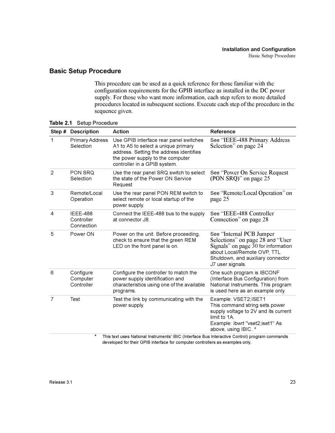
This procedure can be used as a quick reference for those familiar with the configuration requirements for the GPIB interface as installed in the DC power supply. For those who want more information, each step refers to more detailed procedures located in subsequent sections. Execute each step of the procedure in the sequence given.
Table 2.1 Setup Procedure
Step # | Description | Action | Reference |
1 | Primary Address | Use GPIB interface rear panel switches | See |
| Selection | A1 to A5 to select a unique primary | Selection” on page 24 |
|
| address. Setting the address identifies |
|
|
| the power supply to the computer |
|
|
| controller in a GPIB system. |
|
2 | PON SRQ | Use the rear panel SRQ switch to select | See “Power On Service Request |
| Selection | the state of the Power ON Service | (PON SRQ)” on page 25 |
|
| Request |
|
3 | Remote/Local | Use the rear panel PON REM switch to | See “Remote/Local Operation” on |
| Operation | select remote or local startup of the | page 25 |
|
| power supply. |
|
4 | Connect the | See | |
| Controller | at connector J8. | Connection” on page 28 |
| Connection |
|
|
5 | Power ON | Power on the unit. Before proceeding, | See “Internal PCB Jumper |
|
| check to ensure that the green REM | Selections” on page 28 and “User |
|
| LED on the front panel is on. | Signals” on page 30 for information |
|
|
| about Local/Remote OVP, TTL |
|
|
| Shutdown, and auxiliary connector |
|
|
| J7 user signals. |
6 | Configure | Configure the controller to match the | One such program is IBCONF |
| Computer | power supply identification and | (Interface Bus Configuration) from |
| Controller | characteristics using one of the available | National Instruments. This program |
|
| programs. | is used here as an example only. |
|
|
|
|
7 | Test | Test the link by communicating with the | Example: VSET2;ISET1 |
|
| power supply. | This command string sets power |
|
|
| supply voltage to 2V and its current |
|
|
| limit to 1A. |
Example: ibwrt "vset2;iset1" As above, using IBIC. *
*This text uses National Instruments' IBIC (Interface Bus Interactive Control) program commands developed for their GPIB interface for computer controllers as examples only.
Release 3.1 | 23 |