Installation and Configuration
Initial Inspection
CAUTION
Use proper static control techniques to avoid damage to
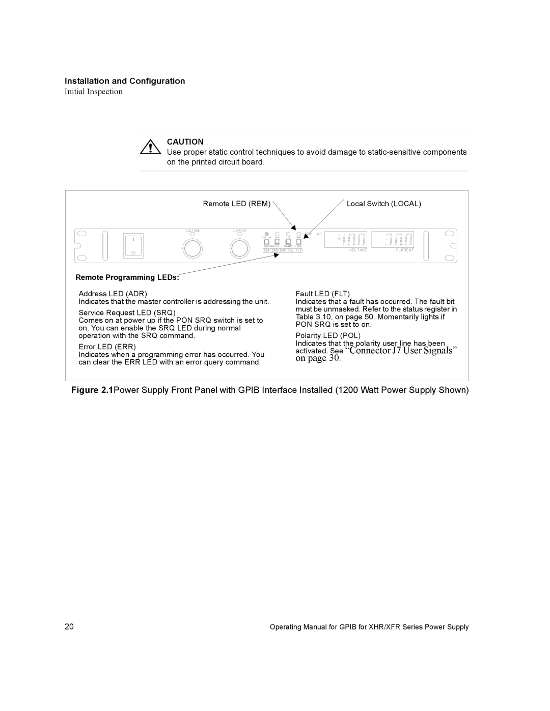
Remote LED (REM) | Local Switch (LOCAL) |
Remote Programming LEDs:
Address LED (ADR)
Indicates that the master controller is addressing the unit.
Service Request LED (SRQ)
Comes on at power up if the PON SRQ switch is set to on. You can enable the SRQ LED during normal operation with the SRQ command.
Error LED (ERR)
Indicates when a programming error has occurred. You can clear the ERR LED with an error query command.
Fault LED (FLT)
Indicates that a fault has occurred. The fault bit must be unmasked. Refer to the status register in Table 3.10, on page 50. Momentarily lights if PON SRQ is set to on.
Polarity LED (POL)
Indicates that the polarity user line has been
activated. See “Connector J7 User Signals” on page 30.
Figure 2.1Power Supply Front Panel with GPIB Interface Installed (1200 Watt Power Supply Shown)
20 | Operating Manual for GPIB for XHR/XFR Series Power Supply |