Installation and Configuration
Initial Inspection
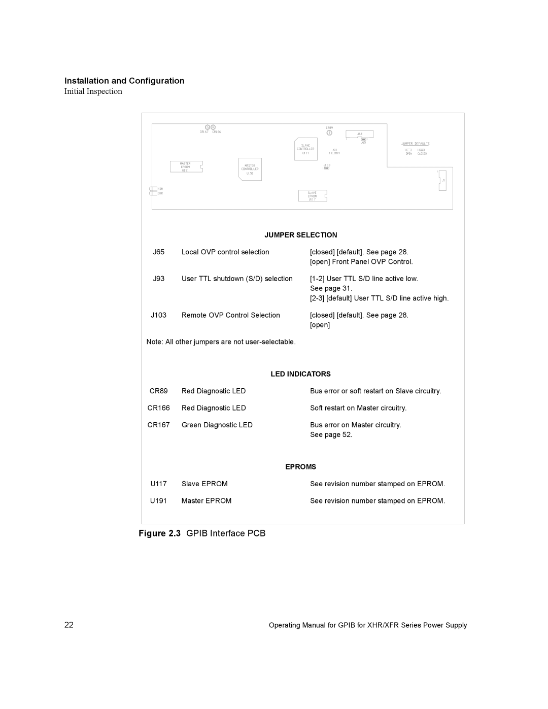
| JUMPER SELECTION | |
J65 | Local OVP control selection | [closed] [default]. See page 28. |
|
| [open] Front Panel OVP Control. |
J93 | User TTL shutdown (S/D) selection | |
|
| See page 31. |
|
| |
J103 | Remote OVP Control Selection | [closed] [default]. See page 28. |
|
| [open] |
Note: All other jumpers are not
|
| LED INDICATORS |
CR89 | Red Diagnostic LED | Bus error or soft restart on Slave circuitry. |
CR166 | Red Diagnostic LED | Soft restart on Master circuitry. |
CR167 | Green Diagnostic LED | Bus error on Master circuitry. |
|
| See page 52. |
|
| EPROMS |
U117 | Slave EPROM | See revision number stamped on EPROM. |
U191 | Master EPROM | See revision number stamped on EPROM. |
Figure 2.3 GPIB Interface PCB
22 | Operating Manual for GPIB for XHR/XFR Series Power Supply |