CHAPTER2 Ethernet Unit
2-14-2 Modular connector
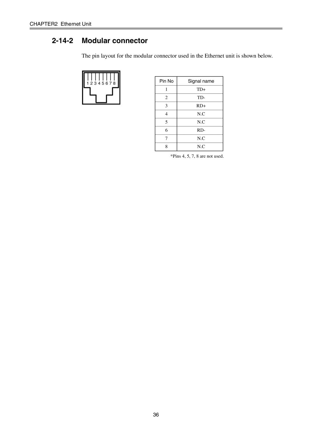
The pin layout for the modular connector used in the Ethernet unit is shown below.
1 2 3 4 5 6 7 8 | Pin No | Signal name |
|
| |
| 1 | TD+ |
|
|
|
| 2 | TD- |
|
|
|
| 3 | RD+ |
|
|
|
| 4 | N.C |
|
|
|
| 5 | N.C |
|
|
|
| 6 | RD- |
|
|
|
| 7 | N.C |
|
|
|
| 8 | N.C |
|
|
|
*Pins 4, 5, 7, 8 are not used.
36
